Clamping device for alignment of optical axis of compound wave plate

A clamping device and composite wave plate technology, applied in the direction of installation, optics, optical components, etc., can solve the problem of no wave plate clamping and its motion control.

Active Publication Date: 2014-07-30
HUAZHONG UNIV OF SCI & TECH
View PDF5 Cites 0 Cited by
  • Summary
  • Abstract
  • Description
  • Claims
  • Application Information

AI Technical Summary

Problems solved by technology

The alignment method of Collins et al. provides a method for precise alignment of the composite wave plate, but does not describe in detail the clamping of the wave plate and its motion control

Method used


Image

  • Clamping device for alignment of optical axis of compound wave plate
  • Clamping device for alignment of optical axis of compound wave plate
  • Clamping device for alignment of optical axis of compound wave plate

Examples


Embodiment Construction

[0021] The structure and function of the clamping device for aligning the optical axis of the composite wave plate provided by the present invention will be further described in detail below in conjunction with the accompanying drawings:

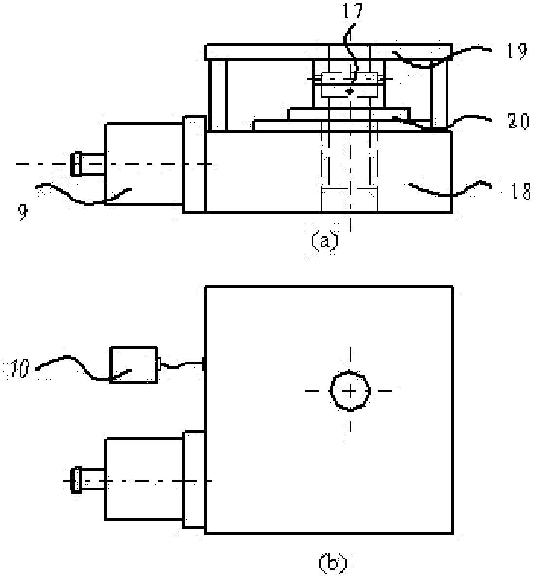
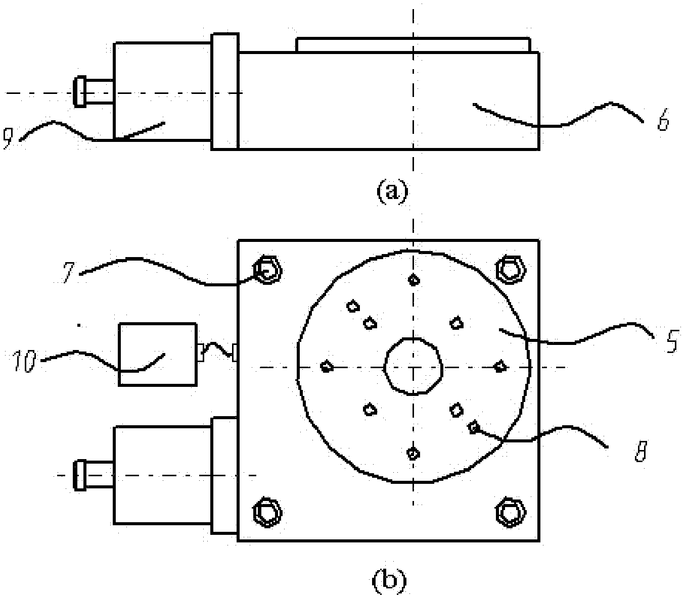
[0022] like figure 1 As shown, the clamping device for aligning the optical axis of the composite wave plate provided by the present invention includes an electrically controlled rotary table 18 , a fixed wave plate chuck 19 and a rotating wave plate chuck 20 .

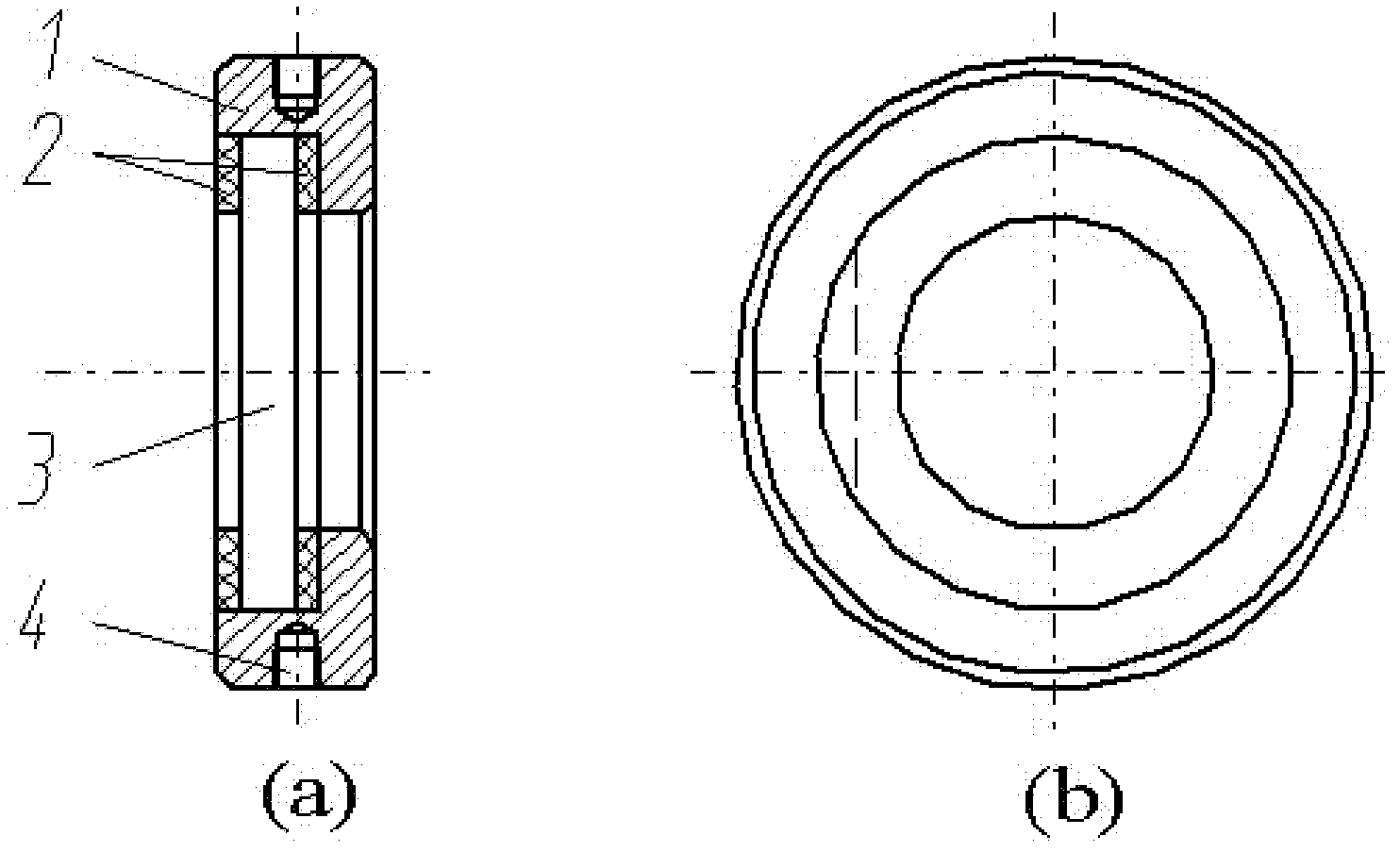
[0023] Waveplates are precision optical components. Usually, the crystal material used to make waveplates is brittle and fragile, and it is easy to damage the chip if it is directly clamped. In order to facilitate wafer clamping, specially designed wafer holders are necessary. The present invention adopts the wave plate support 17 to support and protect the wave plate, so as to facilitate the smooth operation of wave plate clamping and alignment.

[0024] In order to align the opt...


PUM


Abstract

The invention discloses a clamping device for aligning the optical axis of a composite wave plate. The device includes an electronically controlled rotary table, a fixed wave plate chuck and a rotating wave plate chuck; the wave plate bracket is installed on the electrically controlled rotating The fixed wave plate chuck is connected with the base of the electric control rotary table, and the rotating wave plate chuck is connected with the turntable of the electric control rotary table. When in use, install the wave plate holder with the chip on the fixed wave plate card plate and rotating wave plate chuck. The clamping device provided by the present invention can realize the clamping of each wafer forming the composite wave plate when the optical axis of the composite wave plate is aligned with high precision, and ensure high-precision and high-resolution relative rotation between different wafers. Compared with the existing wave plate fixture, the clamping device provided by the present invention can not only realize the clamping and precise positioning of the two wafers, but also enable the relative rotation between the two wafers with high precision and high resolution, which is more suitable for Alignment process for the optical axis of the complex wave plate.

Description

technical field [0001] The invention belongs to the field of design and manufacture of optical instrument components, and in particular relates to a clamping device for aligning the optical axes of a composite wave plate, which is suitable for precisely aligning the optical axes of two or more wafers in a composite wave plate Clamping and motion control of each wafer during calibration. Background technique [0002] Wave plate (also can be referred to as chip. In the present invention, we claim that the wave plate that is made up of two or more wafers is a compound wave plate, and the single wave plate that claims to form a compound wave plate is a chip, to show difference. In not When making a special distinction, the composite wave plate and the wafer are collectively referred to as the wave plate.) is an optical element commonly used in the field of optical instrument design and optical measurement, which can make the two perpendicular components of polarized light produc...

Claims


Application Information

Patent Timeline
Patent Type & Authority Patents(China)
IPC IPC(8): G02B7/00G02B27/28
Inventor 刘世元陈修国谷洪刚张传维
Owner HUAZHONG UNIV OF SCI & TECH
Why Eureka
Try Eureka