Finite element modeling method for hub of megawatt wind generating set

A technology for a wind turbine and a modeling method, which is applied in the fields of electrical digital data processing, special data processing applications, instruments, etc., can solve the problems of low work efficiency, time-consuming, and time-consuming, so as to improve work efficiency and improve Reliability, the effect of reducing workload

Inactive Publication Date: 2012-06-20
BAODING TIANWEI WIND POWER TECH
View PDF2 Cites 10 Cited by
  • Summary
  • Abstract
  • Description
  • Claims
  • Application Information

AI Technical Summary

Problems solved by technology

However, the disadvantage of this is that it assumes that when a certain load component of a certain blade reaches the maximum, the hub bears the maximum ultimate load
To do so, it is necessary to apply six load components (Mx, My, Mz, Fz, Fy, Fz) to the root of each blade for calculation. For a fan with three blades, it is necessary to perform 18 load calculations on the model. Generally, Said that the finite element model of the wheel hub is very large, and it takes a certain amount of time to calculate each load, which is time-consuming and inefficient

Method used


Image

  • Finite element modeling method for hub of megawatt wind generating set
  • Finite element modeling method for hub of megawatt wind generating set
  • Finite element modeling method for hub of megawatt wind generating set

Examples


Embodiment Construction

[0015] The present invention will be further described through the embodiments below in conjunction with the accompanying drawings.

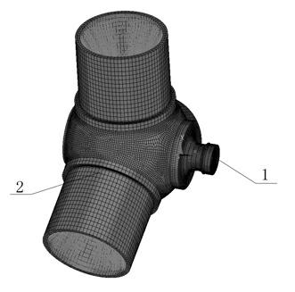
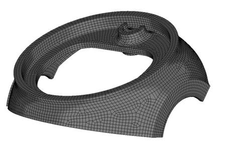
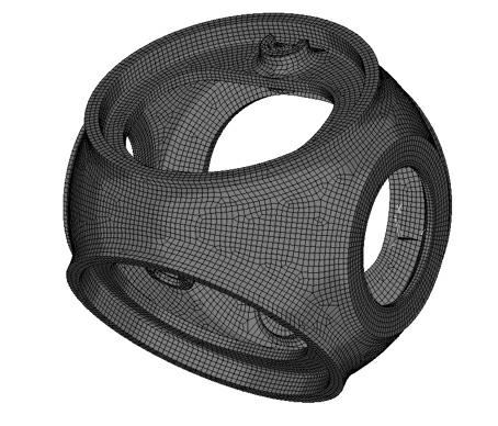
[0016] Refer to attached figure 1 , 4 , finite element unit 1, finite element unit 2, and finite element unit 3 are rotationally symmetric, that is, finite element unit 1 is copied by 120 degrees clockwise from finite element unit 1, and finite element unit 3 is formed by finite element unit 1 Rotated 240 degrees clockwise and copied.

[0017] For example, it is necessary to calculate the stress of the finite element element under various limit conditions. First, apply a unit load on the root of the blade 1, and then record the stresses of finite element element 1, finite element element 2, and finite element element 3 respectively. Then, according to the rotational symmetry, if the same load exists at the blade 2 position, the stress contribution of this load to the finite element element 1 is equivalent to the stress generated at the finite...


PUM


Abstract

The invention relates to a finite element modeling method for a hub of a megawatt wind generating set, and belongs to the technical field of wind power generation. The technical scheme comprises the following steps of: modeling a 1/3 model of the spherical hub according to the symmetry of the spherical hub to form a finite element model of the 1/3 model, and rotating finite element model of the 1/3 model to form a finite element model of the whole hub; and performing calculation and strength checking by utilizing the rotational symmetry of the spherical hub, wherein the rotational symmetry refers to that hub stress nephograms formed by applying a load on one blade and applying a load on another blade can be completely superposed after rotating 120 or 240 degrees. The method has the advantages that: for analysis on the ultimate strength of the hub, all ultimate load working conditions can be taken into account, and limitation on the condition that a certain load component reaches maximum is avoided, so that calculation reliability and comprehensiveness are improved, and a calculated amount is decreased; and for analysis on fatigue strength, the workload of calculation is greatly reduced, and working efficiency is improved.

Description

technical field [0001] The invention relates to a finite element modeling method for a hub of a megawatt-level wind power generating set, belonging to the technical field of wind power generation. Background technique [0002] At present, in the field of wind power technology, the main structural form of the wind turbine hub is "spherical". Due to the complexity of its structure, it cannot be equivalently analyzed like blades, main shafts, towers and other slender parts. Its The strength analysis (ultimate strength and fatigue strength) is mainly carried out by using the finite element method, as shown in the attached figure 1 shown. In the model, it mainly includes the main body of the hub, the pitch bearing, the blade prosthesis, and some parts of the main shaft. The basis for establishing the blade prosthesis and part of the main shaft is Saint-Venant’s principle, so that the stress at the connecting part of the hub is also close to reality. A full displacement constra...

Claims


Application Information

Patent Timeline
Patent Type & Authority Applications(China)
IPC IPC(8): G06F17/50
Inventor 王广庆李曼鲁志平冯红岩王林麻磊
Owner BAODING TIANWEI WIND POWER TECH
Why Eureka
Try Eureka