Eureka AIR delivers breakthrough ideas for toughest innovation challenges, trusted by R&D personnel around the world.

Method and device for machining airfoil hole on two-layer beam lining girder of automobile frame

A technology of automobile frame and processing method, which is applied in the directions of feeding device, positioning device, storage device, etc., can solve the problems of difficult production of multiple varieties, small batches, and multiple batches, large scale, and low processing efficiency.

Inactive Publication Date: 2014-06-25
WUZHENG
View PDF5 Cites 0 Cited by
  • Summary
  • Abstract
  • Description
  • Claims
  • Application Information

AI Technical Summary

Problems solved by technology

[0002] In the past, the drilling method of longitudinal beam flat material radial drilling machine was used to process the wing surface of automobile longitudinal beam. Due to the limitation of equipment, the method of drilling processing has many disadvantages: poor processing accuracy and low processing efficiency, and needs to be customized for different products. Manufacture a variety of drilling jigs, the production preparation period is long, it is difficult to adapt to the production rhythm of multi-variety, small batch, multi-batch products, and the bonding strength of the longitudinal beam after drilling is very low after riveting
At present, most large-scale manufacturers use three-sided CNC punching equipment to punch the holes on the frame longitudinal beams. This processing method has complex structure, large scale and high cost, and is difficult to be suitable for multi-variety, small-batch and multi-batch production. Production needs

Method used


Image

  • Method and device for machining airfoil hole on two-layer beam lining girder of automobile frame

Examples


Embodiment Construction

[0018] The present invention will be further explained below in conjunction with the drawings and embodiments. In the following detailed description, only certain exemplary embodiments of the present invention are described by way of illustration. Needless to say, those of ordinary skill in the art can realize that the described embodiments can be modified in various ways without departing from the spirit and scope of the present invention. Therefore, the drawings and description are illustrative in nature, and are not used to limit the protection scope of the claims.

[0019] The method for processing double-layer beam lining beam wing hole of automobile frame includes the following steps:

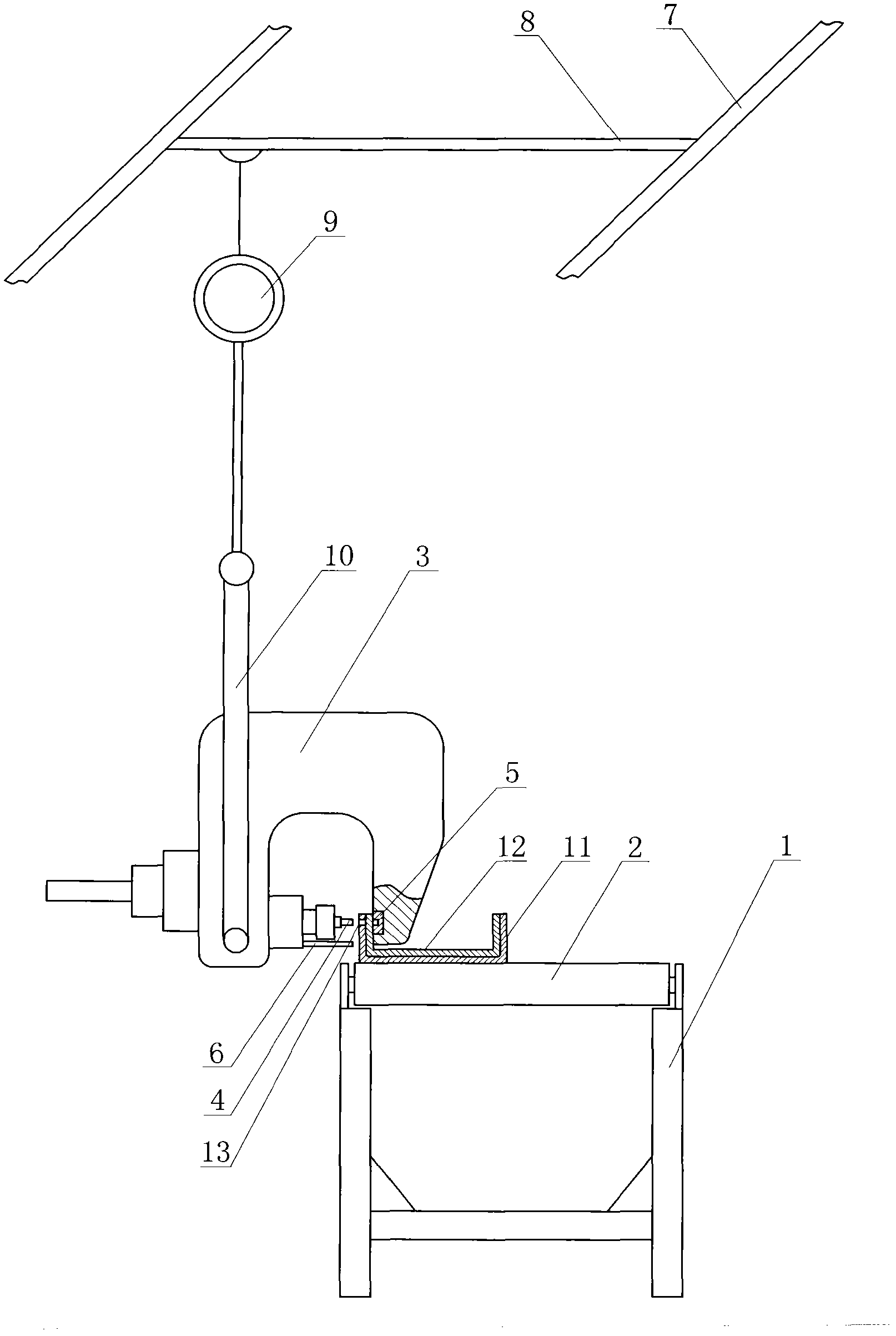
[0020] Step 1. The plate of the main beam of the double-layer beam is fed into a flat-plate numerically controlled automatic punching and punching machine, and the web and wing holes of the double-layer beam main beam are completed by the flat-plate numerically controlled automatic punching a...


PUM


Abstract

The invention discloses a method for machining an airfoil hole on a two-layer beam lining girder of an automobile frame, and the method comprises the following steps of: machining the ventral hole and airfoil hole of a dual-layer beam main girder by virtue of a panel numerical-control automatic punching machine at one step; machining the ventral hole of the dual-layer beam lining girder by virtue of the panel numerical-control automatic punching machine at one step; positioning the holes by using a ventral standard process and welding at a middle frequency; feeding the dual-layer beam main girder and the dual-layer beam lining girder into a pressure machine and carrying out punch forming; placing the dual-layer beam main girder and the dual-layer beam lining girder, which are formed by the pressure machine, on a device for machining the airfoil hole of the lining girder; and machining the airfoil hole on the lining girder by using the airfoil hole on the dual-layer beam main girder as a standard. By using the airfoil hole on the dual-layer beam main girder as the standard, the holes with equal diameter are rapidly machined. The method for machining the airfoil hole on the two-layer beam lining girder of the automobile frame disclosed by the invention has the advantages of convenience for positioning, high positioning precision and rapidness, simplicity and convenience in operation. The machined airfoil hole of the lining girder is high in precision. The requirement on the concentricity of the airfoil holes of the dual-layer beam main girder and the dual-layer beam lining girder is ensured. The method disclosed by the invention is beneficial to the sufficient riveting when the automobile frame is riveted, so that the adhering strength is high after a longitudinal beam is riveted, thus the product quality is improved.

Description

Technical field [0001] The invention relates to a method for processing the wing hole of a double-layer beam lining beam of an automobile frame, and a processing device used in the processing method. Background technique [0002] In the past, automobile longitudinal beam wing hole processing used the method of longitudinal beam flat material radial drilling machine to drill. Due to the limitation of equipment, the selection of drilling method has many disadvantages: poor processing accuracy, low processing efficiency, and need to target different products Manufacturing a variety of drilling dies, the production preparation cycle is long, it is difficult to adapt to the production cycle of multi-variety, small batch, multi-batch products, and the longitudinal beam after drilling is riveted, the bonding strength of the longitudinal beam is very low. At present, most large manufacturers use three-sided CNC punching equipment to punch holes on the frame rails. This processing method ...

Claims


Application Information

Patent Timeline
Patent Type & Authority Patents(China)
IPC IPC(8): B21D28/24B21D43/08
Inventor 李瑞川高曰纯陈常友孙丽强仲臣臣
Owner WUZHENG
Why Eureka
Eureka Blog
Learn More