A CNC grinding machine

A technology of CNC grinding machine and frame, applied in the field of machinery, can solve the problems of inconvenient operation of operators, unfavorable production and processing, large floor space, etc., and achieve the effect of smooth conveying process, high work efficiency and small floor space

Inactive Publication Date: 2017-01-11
NINGBO MEIDE ROBOT
View PDF6 Cites 0 Cited by
  • Summary
  • Abstract
  • Description
  • Claims
  • Application Information

AI Technical Summary

Problems solved by technology

[0003] Existing grinding machines are generally divided into a processing area and a feeding area, wherein the processing area and the feeding area are arranged on the frame in parallel and transversely, that is to say, the processing area is set at the left end of the frame, and the feeding area is set at the right end. This layout not only exists There is a problem of large floor area, and it also makes the processing area and the feeding area face the operators at the same time, which has certain potential safety hazards
[0004] In addition, the existing grinding machine workbenches are all fixedly connected, and the grinding tools can only slide in a straight line in the front and rear horizontal directions, which is not conducive to production and processing, and makes it inconvenient for operators to operate

Method used


Image

  • A CNC grinding machine
  • A CNC grinding machine
  • A CNC grinding machine

Examples


Embodiment Construction

[0036] The following are specific embodiments of the present invention and in conjunction with the accompanying drawings, the technical solutions of the present invention are further described, but the present invention is not limited to these embodiments.

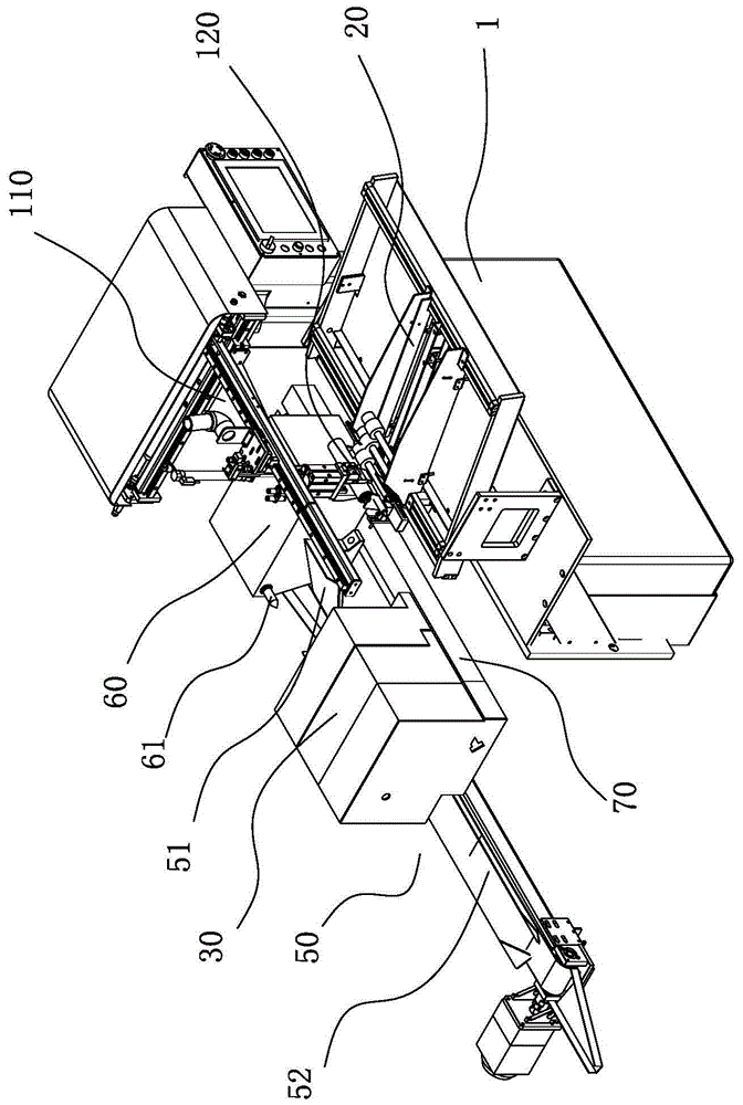
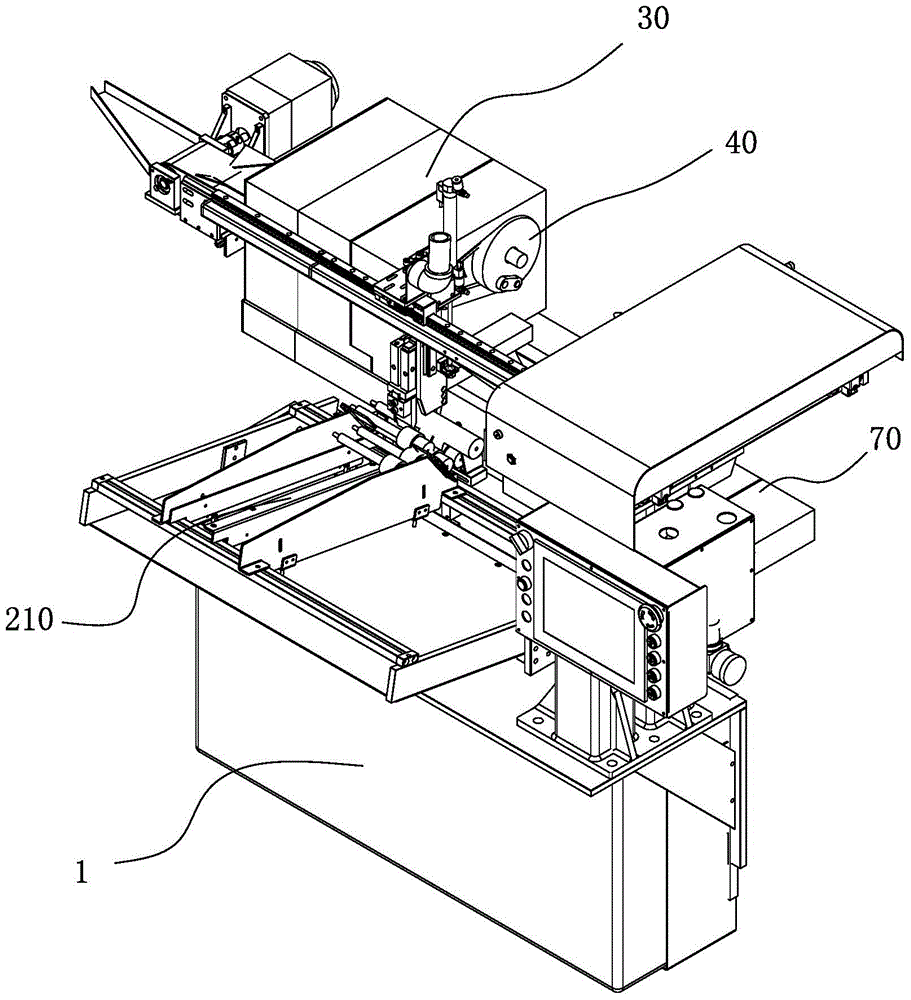
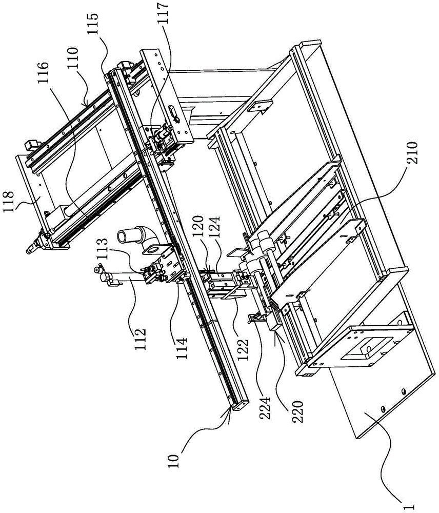
[0037] Such as Figure 1 to Figure 14As shown, the CNC grinding machine includes a frame 1, a grinding tool and a workbench 70 movably installed on the frame 1. The frame 1 is divided into a feeding area and a processing area from front to back. The material mechanism 20 and the material feeding mechanism 10 are provided with a spindle box 30 and a material unloading mechanism 50 in the processing area. And it can linearly reciprocate between the incoming material mechanism 20 and the spindle box 30, a floating chuck 40 is installed on the spindle box 30, and a top material seat 60 is also provided on the frame 1 and the top material seat 60 is located at the spindle box 30 Right in front, the abrasive tool is installed d...


PUM


Abstract

The invention provides a CNC (computer numerical control) grinding machine and belongs to the technical field of machinery. The CNC grinding machine comprises a frame, a grinding tool and a bench movably mounted on the frame. The frame includes a conveying area and a processing area sequentially from front to rear. An incoming mechanism and a conveying mechanism are disposed in the conveying area. A spindle box and a discharging mechanism are disposed in the processing area. The discharging mechanism and the incoming mechanism are disposed on two sides of the spindle box. The conveying mechanism is disposed over the incoming mechanism and can linearly reciprocate between the incoming mechanism and the spindle box. A floating chuck is mounted on the spindle box. The frame is provided with an ejector base arranged right in front of the spindle box. The grinding tool is movably mounted right in rear of the spindle box. The spindle box is fixedly connected with the bench. The ejector base is disposed over the bench. The frame is further provided with a first drive motor and a second drive motor; the first drive motor can control the grinding tool to linearly move in the horizontal direction; the second drive motor can control the bench to linearly slide. The CNC grinding machine has the advantages of high automation level and operational convenience.

Description

technical field [0001] The invention belongs to the technical field of machinery, and in particular relates to a numerical control grinding machine. Background technique [0002] A grinder is a machine tool that uses abrasive tools to grind the surface of a workpiece. Most grinding machines use high-speed rotating grinding wheels for grinding, and a few use other abrasive tools such as oil stones, abrasive belts, and free abrasives for processing. [0003] Existing grinding machines are generally divided into a processing area and a feeding area, wherein the processing area and the feeding area are arranged on the frame in parallel and transversely, that is to say, the processing area is set at the left end of the frame, and the feeding area is set at the right end. This layout not only exists Not only does it occupy a large area, but it also makes the processing area and the feeding area face the operators at the same time, which poses certain safety hazards. [0004] In ...

Claims


Application Information

Patent Timeline
Patent Type & Authority Patents(China)
IPC IPC(8): B24B27/00B24B41/00B24B41/06
CPCB24B27/00B24B41/005B24B41/062
Inventor 翁海明
Owner NINGBO MEIDE ROBOT
Why Eureka
Try Eureka