Device and method capable of reducing interlayer burrs during making holes for aircraft assembly

An aircraft assembly and interlayer technology, which is applied in the direction of manufacturing tools, portable drilling rigs, drilling/drilling equipment, etc., can solve the problems of complex hole making process and poor effect, achieve reasonable device structure, reduce the workload of hole making, and improve The effect of drilling efficiency and quality

Inactive Publication Date: 2012-06-27
NANJING UNIV OF AERONAUTICS & ASTRONAUTICS
View PDF7 Cites 12 Cited by
  • Summary
  • Abstract
  • Description
  • Claims
  • Application Information

AI Technical Summary

Problems solved by technology

[0006] The purpose of the present invention is to invent a device and method capable of reducing interlayer burrs in aircraft assembly for hole-making in order to prevent the burr from entering the interlayer when the existing interlayer is drilled.

Method used


Image

  • Device and method capable of reducing interlayer burrs during making holes for aircraft assembly
  • Device and method capable of reducing interlayer burrs during making holes for aircraft assembly
  • Device and method capable of reducing interlayer burrs during making holes for aircraft assembly

Examples


Embodiment 1

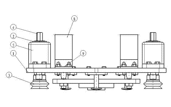
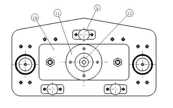
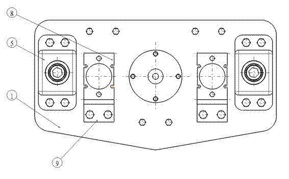
[0039] Such as Figure 1-4 shown.

[0040] A device capable of reducing interlayer burrs during aircraft assembly hole making, which includes a main frame plate 1, a spherical joint bearing 2, a vacuum suction cup 3, a suction cup connecting shaft 4, an auxiliary mounting frame 5, a positioning shaft 6, and a limit rubber ring 7 , cylinder 8, cylinder auxiliary mounting plate 9, pressure foot frame 10, pressure foot 11 and drill riveting sleeve 12, such as figure 1 As shown, the vacuum chucks 3 (the number is at least two) are balanced and fixedly arranged on the main frame plate 1, so that the main frame plate 1 can be fixed on the machined surface of the aircraft through the suction force of the vacuum chucks 3, The vacuum suction cup 3 can be connected with the vacuum generating device through the trachea so that the suction cup foot can generate the required suction force, and the adjustment of the vacuum degree of the vacuum generating device can realize the adjustment o...

Embodiment 2

[0044] A kind of method that can reduce interlayer burr when aircraft assembly makes hole it comprises the following steps:

[0045] Step 1: Place and position the device of Example 1 on the surface of the product;

[0046] Step 2: Fix the device of Example 1 on the surface of the aircraft product by controlling the suction cup in turn. At this time, the arc-shaped end faces of the three positioning shafts are in contact with the surface of the aircraft product. The arc-shaped ends of the positioning shafts are covered with rubber, allowing a certain amount The elasticity, so there will be no excessive pressure on the surface of the aircraft product to cause deformation. At this time, the centroid axis of the triangle formed by the three positioning axes coincides with the surface normal of the aircraft product in the working area, that is, the normal alignment of the pressure foot is completed.

[0047] Step 3: Control the pressure switch of the cylinder so that the cylinder...


PUM


Abstract

The invention discloses a device and method capable of reducing interlayer burrs during making holes for aircraft assembly. The device is characterized by comprising a main frame plate (1), at least two vacuum chucks (3), at least three locating shafts (6) and at least two driving cylinders (8), wherein the vacuum chucks (3) are evenly and fixedly arranged on the main frame plate (1); the drivingcylinders (8) are arranged on the main frame plate (1) through a cylinder installation assisting plate (9), output shafts of the driving cylinders (8) are connected with a pressure foot frame (10), and a pressure foot (11) is arranged on the pressure foot frame (10); a drilling and riveting sleeve (12) is arranged in a central hole of the pressure foot (11), and the tool center of the drilling and riveting sleeve (12) is coincided with the center of the pressure foot (11). The device is simple in structure, covneient to manufacture and capable of greatly reducing interlayer burrs so that technological requirements are met.

Description

technical field [0001] The present invention relates to a device and method for making holes in sandwich panels, in particular to a device and method for making holes that can reduce burrs from entering between interlayers, and in particular to a device and method that can reduce burrs in interlayers during hole making in aircraft assembly. devices and methods. Background technique [0002] At present, domestic aircraft OEMs still mainly use manual methods for drilling and connection. Especially for commercial airliners with high fatigue life requirements, the main process methods are: first guide the hole, expand the hole, disassemble and deburr, apply glue on the joint surface, install the through-clip for temporary fastening, glue curing, and expand to the final holes to install the fasteners. The process is very complicated and the efficiency is low, especially because the glue curing process takes up equipment and tooling, which seriously affects the efficiency. [0...

Claims


Application Information

Patent Timeline
Patent Type & Authority Applications(China)
IPC IPC(8): B23B45/14B23B49/02
Inventor 王珉鲍益东陈文亮郝小忠曾长王谢苗
Owner NANJING UNIV OF AERONAUTICS & ASTRONAUTICS
Why Eureka
Try Eureka