Rubber mixing machine

A mixer and rubber technology, which is applied in the field of rubber machinery and equipment, can solve the problems of large energy consumption, long mixing time, and large load impact of the internal mixer, so as to reduce energy consumption, facilitate full mixing, and improve production quality Effect

Inactive Publication Date: 2012-06-27
HIMILE MECHANICAL SCI & TECH (SHANDONG) CO LTD
View PDF5 Cites 14 Cited by
  • Summary
  • Abstract
  • Description
  • Claims
  • Application Information

AI Technical Summary

Problems solved by technology

This traditional operation process has many deficiencies: First, the Mooney viscosity and other indicators of rubber mixing are highly volatile, because there are differences in the quality of rubber from different suppliers or different batches of rubber from the same supplier, resulting in fluctuations in the quality of finished tires ; Secondly, it is directly put into the internal mixer in the form of standard rubber block, because the block is larger, the banburying time is longer, the banburying efficiency is low, and the heat generated by banburying is serious at the same time, which is not conducive to stabilizing the quality of the rubber block; again, the standard The rubber block needs to be baked, which consumes a lot of energy. The standard rubber block entering the internal mixer has a great impact on the load of the internal mixer, and the frequency of overhaul of the internal mixer is high.

Method used


Image

  • Rubber mixing machine
  • Rubber mixing machine
  • Rubber mixing machine

Examples


Embodiment Construction

[0020] Below in conjunction with accompanying drawing and embodiment, further elaborate the present invention. In the following detailed description, certain exemplary embodiments of the invention are described by way of illustration only. Needless to say, those skilled in the art would realize that the described embodiments can be modified in various different ways, all without departing from the spirit and scope of the present invention. Accordingly, the drawings and description are illustrative in nature and not intended to limit the scope of the claims.

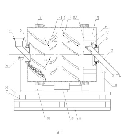
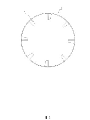
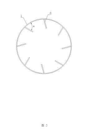
[0021] like figure 1 , figure 2 and image 3 As shown, the rubber mixer includes a control device and a mixing cylinder 1 installed on a support 61. The support 61 is provided with a driving device for driving the rotation of the mixing cylinder 1, and the mixing cylinder 1 is mounted on the support 61. The installation can be provided with a roller set on the support 61, and a known method such as a track correspon...


PUM


Abstract

The invention discloses a rubber mixing machine. The rubber mixing machine comprises a control device and a mixing cylinder which is arranged on a supporting base, wherein a driving device used for driving the mixing cylinder to rotate is arranged on the supporting base; a material inlet and a material outlet are respectively formed at the two ends of the mixing cylinder; a feeding device is arranged at the material inlet; a discharging device is arranged at the material outlet; the driving device, the feeding device and the discharging device are respectively connected with the control device; material mixing blade wings arranged along a feeding spiral direction are respectively arranged in the inner wall of the mixing cylinder; an acute angle material accommodating angle is formed between the material mixing blade wings and the inner wall of the mixing cylinder; and a material stirring hopper is distributed on the inner wall of the mixing cylinder, positioned in the end of the material outlet. Before standard rubber blocks are subjected to banburying and after the standard rubber blocks produced in different batches are cut into small rubber blocks, the small rubber blocks can be fully mixed and homogenized, the production quality is improved, and the energy consumption is reduced.

Description

technical field [0001] The invention relates to a rubber mechanical equipment for mixing and homogenizing rubber blocks, in particular to a device for mixing and homogenizing after crushing different batches of standard rubber blocks before rubber banburying in the tire industry. Background technique [0002] At present, the first process of traditional rubber mixing in the tire industry is rubber drying, which is to heat standard rubber blocks to an appropriate temperature. The second process after that is to put the baked standard rubber block directly into the internal mixer for internal mixing, and add various auxiliary materials during the internal mixing process. This traditional operation process has many deficiencies: First, the Mooney viscosity and other indicators of rubber mixing are highly volatile, because there are differences in the quality of rubber from different suppliers or different batches of rubber from the same supplier, resulting in fluctuations in th...

Claims


Application Information

Patent Timeline
Patent Type & Authority Applications(China)
IPC IPC(8): B29B7/10B29B7/28B29B7/26B29B7/24
Inventor 曹世良陈世伟张增军孙德全
Owner HIMILE MECHANICAL SCI & TECH (SHANDONG) CO LTD
Why Eureka
Try Eureka