Bump split wheel sleeve for steel rolling wheel

A bump-type, steel wheel technology, applied in the direction of roads, road repair, roads, etc., can solve the problems of inability to meet the construction requirements of the construction environment, increase the workload of construction personnel, and single function of rolling steel wheels, and achieve high practical value. , good economy and practicability, the effect of simple structure

Inactive Publication Date: 2014-08-06
CHANGAN UNIV
View PDF6 Cites 0 Cited by
  • Summary
  • Abstract
  • Description
  • Claims
  • Application Information

AI Technical Summary

Problems solved by technology

But nowadays, the rolling steel wheels of static rolling rollers or vibratory rollers widely used in construction have a single function, and the rolling steel wheels used are usually smooth wheels or steel wheels with bumps that cannot or are not easy to disassemble. The actual construction cannot meet the actual needs of the changing construction environment and the continuous improvement of construction requirements
Moreover, the existing steel wheel assembly of the road roller has high manufacturing cost, complicated disassembly and assembly, and difficult replacement
In the actual construction process, frequent transfers of different types of rollers are required, which not only increases the workload of construction personnel, but also brings a series of problems such as prolonging the construction period and increasing construction costs.

Method used


Image

  • Bump split wheel sleeve for steel rolling wheel
  • Bump split wheel sleeve for steel rolling wheel
  • Bump split wheel sleeve for steel rolling wheel

Examples


Embodiment Construction

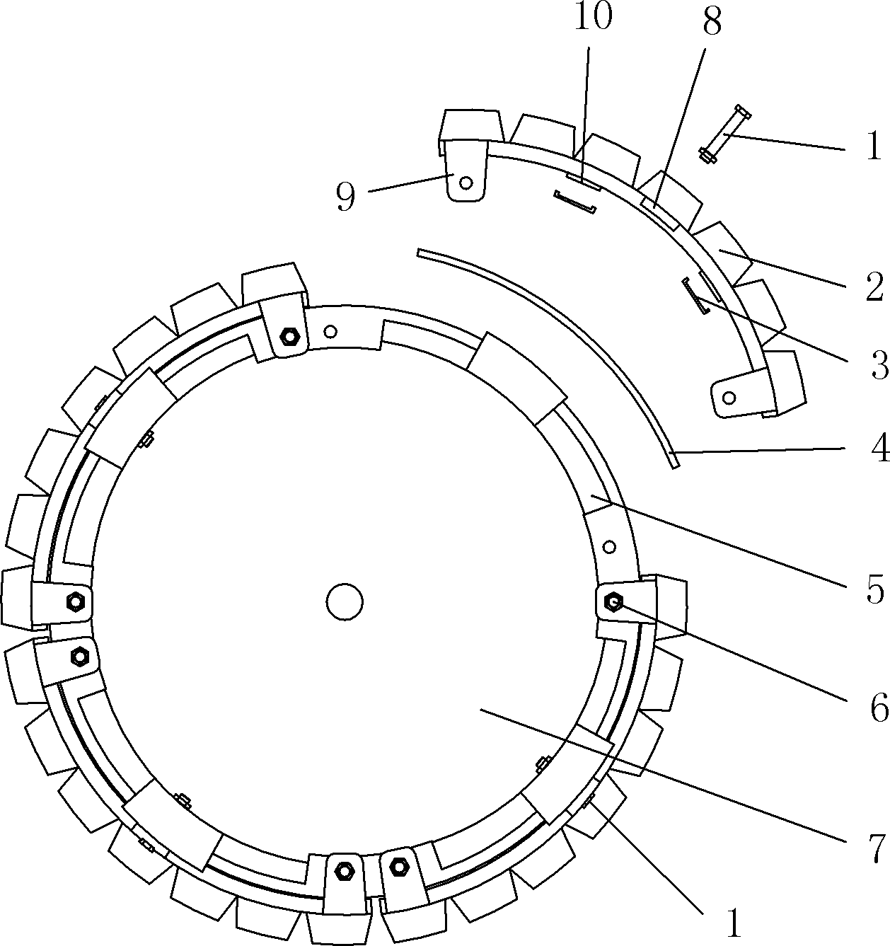
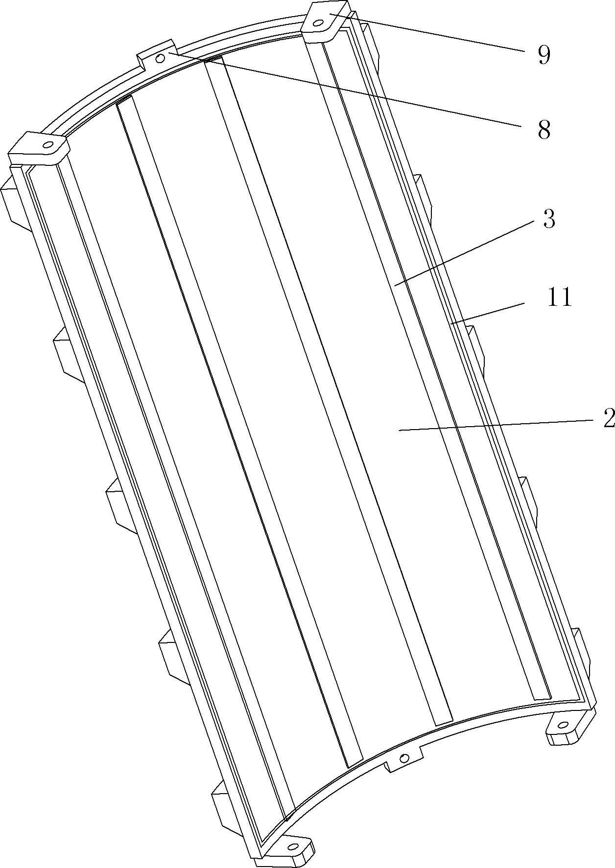
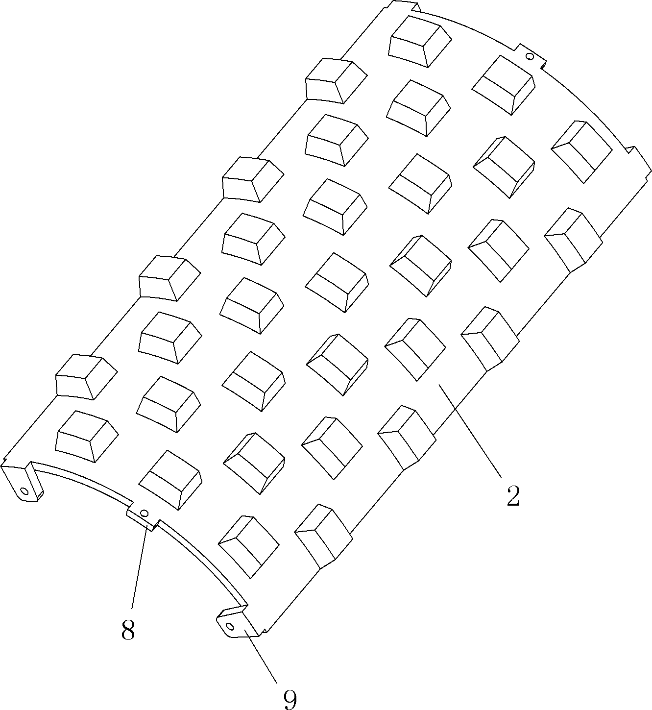
[0031] Such as figure 1 , figure 2 , image 3 and Figure 4 As shown, the present invention includes a plurality of bump plates 2 arranged on the outer side of the rolling steel wheel 7 along the circumferential direction. The structure and size of the plurality of bump plates 2 are the same, and the bump plates 2 are the outer side walls An arc-shaped plate with a plurality of protrusions is arranged on it. The rolling steel wheel 7 is a steel wheel for a slick roller, the steel wheel for a slick roller and a plurality of bump plates 2 form a steel wheel for a cam roller, and the plurality of bump plates 2 are assembled The bump type wheel sleeve is coaxially installed on the outer side of the steel wheel for the slick wheel road roller. The rolling steel wheel 7 is provided with a plurality of light wheel mounting seats 12 which are evenly arranged and fixedly installed on the connecting ends between two adjacent bump plates 2 along the circumferential direction. The f...


PUM


Abstract

The invention discloses a bump split wheel sleeve for a steel rolling wheel. The wheel sleeve comprises a plurality of bump plates arranged on the outer side of the steel rolling wheel along the circumferential direction, wherein a plurality of bump plates have the same structure and size; the steel rolling wheel is a steel wheel for a smooth wheel roller; a steel wheel for a bump roller consists of the steel wheel for the smooth wheel roller and a plurality of bump plates; a plurality of smooth wheel installation seats which are uniformly arranged and used for installing connecting ends between two adjacent bump plates are arranged on the steel rolling wheel along the circumferential direction; a bump plate connecting seat 2 arranged on each smooth wheel installation seat is arranged at each of the front and rear ends of each bump plate; each smooth wheel installation seat is connected with each bump plate connecting seat 2 through a fastening connecting piece 1; and the smooth wheel installation seats have the same number as the bump plates. The wheel sleeve has a simple structure and a good using effect, is reasonable in design, low in input cost and convenient to assemble and disassemble, and meets the actual requirements of changeable construction environments and continuously improved construction requirements, and the bump roller and the smooth wheel roller can be simply, conveniently and quickly switched.

Description

technical field [0001] The invention relates to road compaction construction equipment, in particular to a split wheel sleeve for a bump type rolling steel wheel. Background technique [0002] As a new type of compaction equipment, the bump roller can play an irreplaceable role in the construction process due to its special structure. In recent years, the bump roller has continuously appeared in the fields of transportation, water conservancy and hydropower. in work. But nowadays, the rolling steel wheels of static rolling rollers or vibratory rollers widely used in construction have a single function, and the rolling steel wheels used are usually smooth wheels or steel wheels with bumps that cannot or are not easy to disassemble. The actual construction cannot meet the actual needs of the ever-changing construction environment and the continuous improvement of construction requirements. Moreover, the existing steel wheel assembly of the road roller has high manufacturing ...

Claims


Application Information

Patent Timeline
Patent Type & Authority Patents(China)
IPC IPC(8): E01C19/23
Inventor 赵悟潘旭磊王晓花李奇张敏李海超薛芸冯忠绪
Owner CHANGAN UNIV
Why Eureka
Try Eureka