Manual barring device

A manual turning and positioning device technology, applied in combustion engines, machines/engines, internal combustion piston engines, etc., can solve the problems of high labor intensity, difficult to adjust, and high cost, and achieves low effort to rotate the flywheel, easy maintenance, and manufacturing costs. low effect

Inactive Publication Date: 2012-06-27
CHONGQING WEICHAI ENGINE FACTORY
View PDF6 Cites 5 Cited by
  • Summary
  • Abstract
  • Description
  • Claims
  • Application Information

AI Technical Summary

Problems solved by technology

[0004] 1. Manual lever cranking: the labor intensity of the operator is too high, multiple people are required to crank, the cranking accuracy is poor, and it is difficult to adjust
[0005] 2. The cranking mechanism composed of pneumatic motor and electric motor is used for cranking: the cost of the cranking device is high, the structure is complicated, the space is large, the operation and maintenance are inconvenient, and an external power source is required, and the noise is large
[0006] 3. Ratchet barring: It is necessary to install a special ratchet on the engine flywheel, and install a long and short lever on the base to cooperate with the barring. The manufacturing process of the ratchet is complicated and the cost is high

Method used


Image

  • Manual barring device
  • Manual barring device
  • Manual barring device

Examples


Embodiment Construction

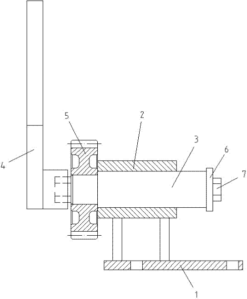
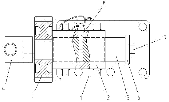
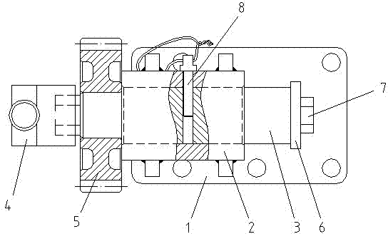
[0018] figure 1 It is a front structural schematic diagram of the manual barring device of the present invention; figure 2 for figure 1 Schematic diagram of the top view structure.

[0019] As shown in the figure, the manual barring device of this embodiment includes a support base 1, a shaft sleeve 2 arranged on the support base 1, and a shaft 3 that is rotatably matched with the shaft sleeve 2 and can slide axially along it, and one end of the shaft 3 A limit device is provided to prevent the shaft from slipping out of the sleeve 2 in the axial direction. The other end of the shaft 3 is detachably provided with a handle rod 4 for driving the shaft to rotate. The shaft section between the handle rod 4 and the sleeve 2 A gear 5 coaxial with the shaft is arranged on the top, and a positioning device for positioning the axial position of the shaft 3 in the sleeve is also included, and the positioning device is detachably connected with the shaft 3 .

[0020] Fix the support ...


PUM


Abstract

The invention discloses a manual barring device, which comprises a supporting seat, a shaft sleeve arranged on the supporting seat and a shaft which is matched rotationally with the shaft sleeve and can slide along axial direction of the shaft sleeve. A limiting device that prevents the shaft from sliding out of the shaft sleeve axially is arranged at one end of the shaft and a handle rod for driving the shaft to rotate is arranged at the other end of the shaft. A gear that is coaxial with the shaft is arranged on a shaft section between the handle rod and the shaft sleeve. The manual barring device further comprises a positioning device for positioning the axial position of the shaft in the shaft sleeve. The positioning device is in detachable connection with the shaft. The supporting seat is fixed on a housing of an engine, the positioning device is disassembled and the shaft is propelled to slide axially so that the gear is engaged with a flywheel ring gear of the engine. The shaft is driven by the handle rod to rotate to bar so that the manual barring device is convenient to operate. The device has a simple structure in parts and low manufacturing cost. Meanwhile, various parts of the device are convenient to disassemble and maintain. The device is free from external powers and low in barring noise, has large-diameter flywheel, saves labor in rotation of the flywheel and is low in labor intensity.

Description

technical field [0001] The invention relates to a barring device. Background technique [0002] Barring refers to turning the crankshaft of the engine several times through the barring device before starting the engine to judge whether the transmission structure is stuck and the resistance increases, so as to avoid damage to the starter motor due to the increase of the starting load. [0003] The existing steering methods are as follows: [0004] 1. Manual lever cranking: the labor intensity of the operator is too high, multiple people are required to crank, the cranking accuracy is poor, and it is difficult to adjust. [0005] 2. Barring mechanism composed of pneumatic motor and electric motor. Barring: the barring device has high cost, complex structure, large space occupation, inconvenient operation and maintenance, and requires an external power source, and the noise is large. [0006] 3. Ratchet type barring: It is necessary to install a special ratchet on the engine ...

Claims


Application Information

Patent Timeline
Patent Type & Authority Applications(China)
IPC IPC(8): F02B79/00
Inventor 刘志刚张渊史长平
Owner CHONGQING WEICHAI ENGINE FACTORY
Why Eureka
Try Eureka