Core fixing cooling radiating system for rotating shaft

A technology for cooling rotating and cooling systems, applied in the cooling field of mechanical parts, which can solve the problems of deformation damage, burnout, and high frequency of heat loss

Inactive Publication Date: 2012-06-27
浙江浙大圆正机电有限公司
View PDF7 Cites 2 Cited by
  • Summary
  • Abstract
  • Description
  • Claims
  • Application Information

AI Technical Summary

Problems solved by technology

[0002] We encountered a rotating shaft working in a thermal field environment, which is easy to be deformed and damaged prematurely, or even burned. The frequency of heat loss is high, and heat dissipation treatment is required to cool down.

Method used


Image

  • Core fixing cooling radiating system for rotating shaft
  • Core fixing cooling radiating system for rotating shaft
  • Core fixing cooling radiating system for rotating shaft

Examples


Embodiment Construction

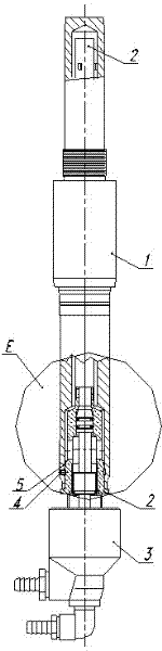
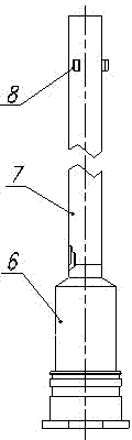
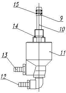
[0011] As shown in the figure, the heat dissipation system for fixed core cooling rotating shaft includes rotating shaft 1, cooling pipe assembly 2, cooling joint assembly 3, inner ball end fastening screw 4 and O-ring 5, wherein cooling pipe assembly 2 includes cooling pipe method Lan 6, cooling pipe 7 and shaft spacer 8; cooling joint assembly 3 includes diverter pipe flange 9, copper pipe 10, elbow joint diverter 11, water inlet pipe joint 12, water outlet pipe joint 13, large sealing ring 14 and The small sealing ring 15; the rotating shaft 1 is set on the outside of the cooling tube assembly 2, and is axially fixed by the inner ball end screw 4; the cooling joint assembly 3 is set on the inside of the cooling tube assembly 2; The inner thread is connected, one end of the inner ball end screw 4 is in the rotating shaft 1, the other end of the inner ball end screw 4 is in the annular groove at the lower part of the cooling pipe assembly 2, and the O-ring 5 is installed in th...


PUM


Abstract

The invention discloses a core fixing cooling radiating system for a rotating shaft, which comprises the rotating shaft, cooling pipe components, a cooling connector component, inner ball-end set screws and O-shaped rings. Each cooling pipe component consists of a cooling pipe flange, a cooling pipe and shaft spacer sleeves, the cooling connector component comprises a flow distributing pipe flange, a red copper pipe, an elbow connection flow distributor, a water inlet pipe connector, a water outlet pipe connector, a large sealing ring and small sealing rings, the rotating shaft is sleeved on outsides of the cooling pipe components, the cooling connector component is sleeved inside the cooling pipe components, and connected with the cooling pipe connectors by internal threads of lower ports of the cooling pipe components, one end of each inner ball-end set screw is arranged in the rotating shaft, the other end of each inner ball-end set screw is disposed in an annular groove of the lower portion of the corresponding cooling pipe component, and the O-shaped rings are mounted in sealing grooves of the lower portions of the cooling pipe components and are arranged among the rotating shaft and the cooling pipe components. The core fixing cooling radiating system is compact in structure and fine in water sealing performance, cooling water can circulate in the rotating shaft in a heat field environment, the temperature of the shaft is reduced, and the service life of the rotating shaft is prolonged.

Description

technical field [0001] The invention relates to the cooling of mechanical parts working in a thermal field environment, in particular to a heat dissipation system for cooling a rotating shaft with a fixed core. Background technique [0002] We encountered a rotating shaft working in a thermal field environment, which is easy to be deformed and damaged prematurely, or even burned. The frequency of heat loss is high, and heat dissipation treatment is required to cool down. However, the upper part of this shaft is installed in the tray body and drives the high-temperature tray to rotate. Due to the narrow space, it is not easy to install cooling equipment near the rotating shaft and on the surface. Considering the heat dissipation problem of the shaft core, we decided to use the shaft core Water cooling method. However, the rotating shaft must rotate when it is working normally. To send cooling water from its lower end to the core of the shaft, it is difficult to consider ...

Claims


Application Information

Patent Timeline
Patent Type & Authority Applications(China)
IPC IPC(8): F25D1/00
Inventor 王跃刚范凤仙
Owner 浙江浙大圆正机电有限公司
Why Eureka
Try Eureka