Optical detection system applicable to absorbed light detection and fluorescence detection

A fluorescence detection and optical detection technology, applied in the direction of fluorescence/phosphorescence, material analysis by optical means, measurement devices, etc., can solve the problems of not being able to perform at the same time, wasting a certain amount of time, positioning errors, etc., to avoid inaccurate positioning and accurate positioning. Sex-enhancing effect

Inactive Publication Date:
View PDF9 Cites 16 Cited by
  • Summary
  • Abstract
  • Description
  • Claims
  • Application Information

AI Technical Summary

Problems solved by technology

[0003] However, in actual implementation, it is found that at present, there is no equipment that can simultaneously detect absorption light and fluorescence, and each of absorption light detection and fluorescence detection requires a separate device to perform, and the existing methods for detecting absorption light or fluorescence The equipment is extremely complicated. In addition, for the same detection tube, after the absorption light detection is completed, it needs to be moved to the equipment for fluorescence detection to perform detection, and the detection tube will cause positioning errors if it is moved back and forth. , affects the accuracy of the detection results, and it takes a certain amount of time to move, so the absorption light detection and the fluorescence detection cannot be carried out at the same time, and it is impossible to detect each substance to be detected at the same time at the same time, and it is impossible to provide researchers with various substances to be detected Status information displayed at the same time

Method used


Image

  • Optical detection system applicable to absorbed light detection and fluorescence detection
  • Optical detection system applicable to absorbed light detection and fluorescence detection

Examples


Embodiment Construction

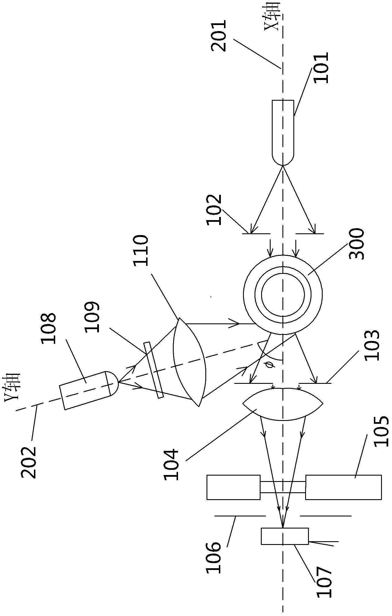
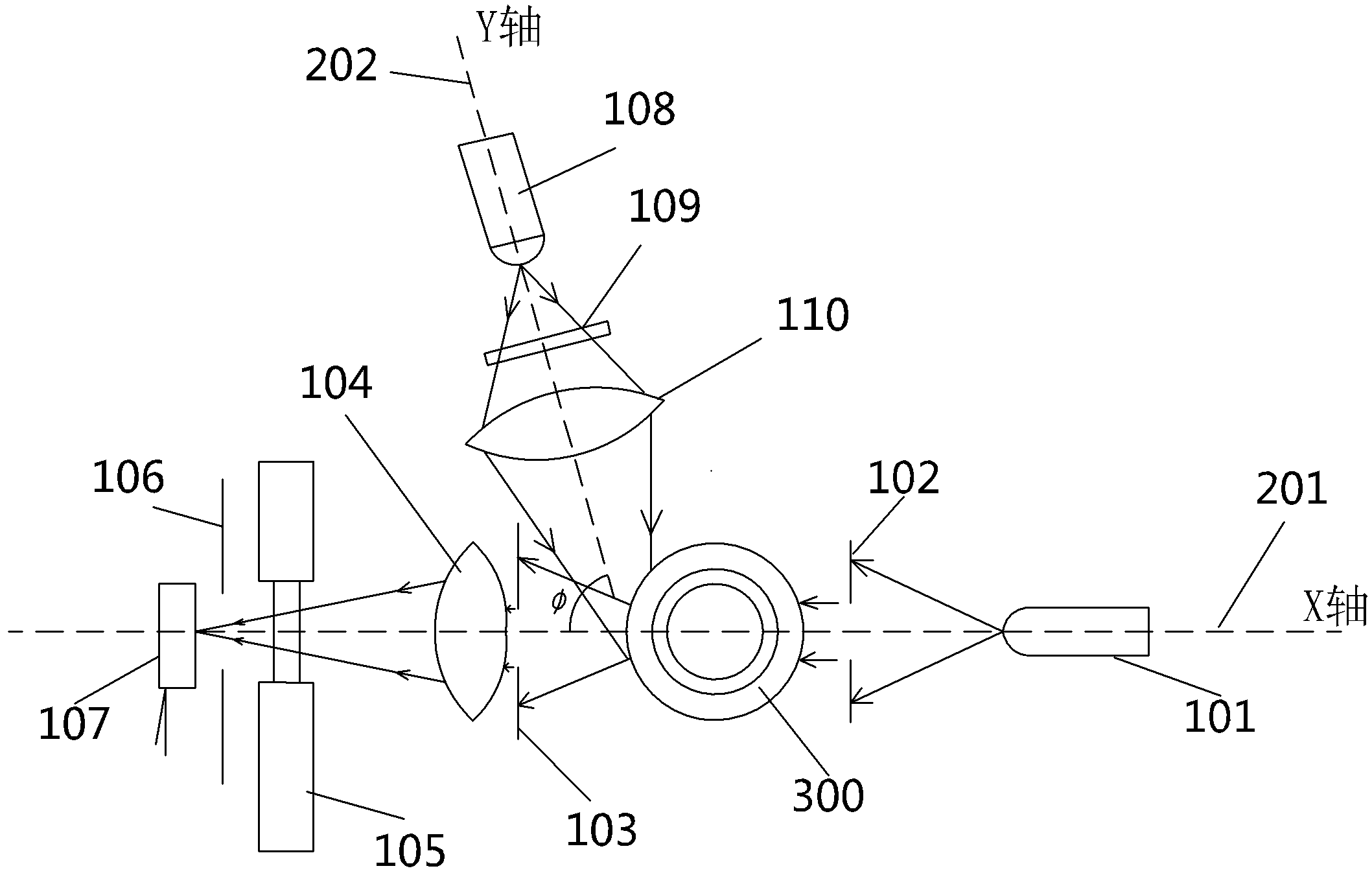
[0014] like figure 1 As shown, the optical detection system suitable for absorption light detection and fluorescence detection of the present invention includes a cold light source 101, a first incident slit 102, a second incident slit 103, a first converging lens 104, a filter converter 105, a second Three incident slits 106, a photodetector 107, a halogen lamp 108, a first optical filter 109 and a second converging lens 110, the cold light source 101, the first incident slit 102, the second incident slit 103, the The first converging lens 104, the third incident slit 106, and the photodetector 107 are sequentially coaxially arranged on the X-axis 201, and a detection tube 300 is placed between the first incident slit 102 and the second incident slit 103 , the filter converter 105 is arranged between the first converging lens 104 and the third incident slit 106, the halogen lamp 108, the first filter 109, and the second converging lens 110 are arranged coaxially in sequence ...


PUM

PropertyMeasurementUnit
angleaaaaaaaaaa

Abstract

The invention discloses an optical detection system applicable to absorbed light detection and fluorescence detection, which comprises a cold light source, a first entrance slit, a second entrance slit, a third entrance slit, a first converging lens, a second converging lens, an optical filter converter, a photoelectric detector, a halogen lamp and a first optical filter. The cold light source, the first entrance slit, the second entrance slit, the first converging lens, the third entrance slit and the photoelectric detector are arranged on the X-axis coaxially sequentially, a detection tube holding to-be-detected substance is arranged between the first entrance slit and the second entrance slit, the optical filter converter provided with a second optical filter and a third optical filter is arranged between the first converging lens and the third entrance slit, and the halogen lamp, the first optical filter and the second converging lens are sequentially arranged on the Y-axis coaxially. The optical detection system can be used for absorbed light detection and fluorescence detection simultaneously, the detection tube is fixed during the absorbed light detection and fluorescence detection, and accordingly detection results of the optical detection system are high in accuracy.

Description

technical field [0001] The invention relates to an optical detection system, in particular to an optical detection system which is used in an automatic blood analyzer and can be used for light absorption detection and fluorescence detection. Background technique [0002] At present, the dry blood cell analyzer generally adopts the centrifugal principle when detecting the content of red blood cells, white blood cells, and platelets in human blood, that is, adding the human blood to be tested into the detection tube containing the corresponding color reagent and fluorescent substance. The detection tube is centrifuged, and the different material components in the blood are layered, and they are distributed in the corresponding areas in the detection tube. Different areas display different colors, so that the corresponding detection methods are detected by absorbing light detection methods and fluorescence detection methods. Substances were quantified. [0003] However, in act...

Claims


Application Information

Patent Timeline
Patent Type & Authority Applications(China)
IPC IPC(8): G01N21/17G01N21/64
Inventor 范宏艳
Why Eureka
Try Eureka