Floating junction solar cell back passivation structure based on heterojunction and preparation technology thereof

A technology for solar cells and preparation processes, applied in sustainable manufacturing/processing, circuits, photovoltaic power generation, etc., can solve the problems of energy band mismatch at heterojunctions and affect the collection efficiency of photogenerated holes, and achieve low surface recombination rate , avoid the effect of high temperature process and high open circuit voltage

Active Publication Date: 2012-06-27
TRINA SOLAR CO LTD
View PDF4 Cites 6 Cited by
  • Summary
  • Abstract
  • Description
  • Claims
  • Application Information

AI Technical Summary

Problems solved by technology

Both the P+P and P-N junctions of this structure are realized by the heterojunction film on the back of the battery. Like the HIT battery, the heterojunction amorphous silicon is used as both the rear passivation layer and the back electrode layer, so there is also a heterojunction The energy band mismatch problem at the position affects the collection efficiency of photogenerated holes

Method used


Image

  • Floating junction solar cell back passivation structure based on heterojunction and preparation technology thereof
  • Floating junction solar cell back passivation structure based on heterojunction and preparation technology thereof
  • Floating junction solar cell back passivation structure based on heterojunction and preparation technology thereof

Examples


Embodiment Construction

[0031] The present invention will now be described in further detail in conjunction with the accompanying drawings and preferred embodiments. These drawings are all simplified schematic diagrams, which only illustrate the basic structure of the present invention in a schematic manner, so they only show the configurations related to the present invention.

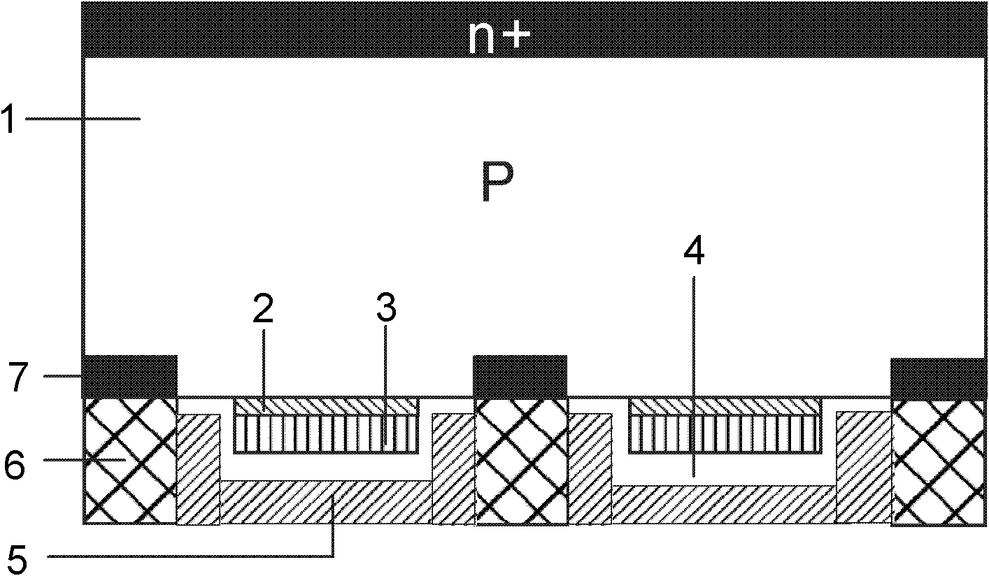
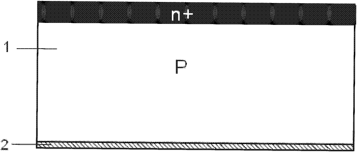
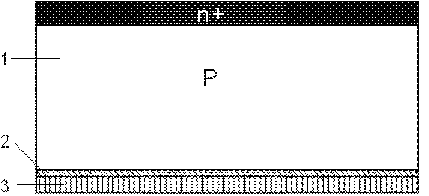
[0032] The following takes a P-type crystalline silicon substrate as an example to describe how to realize the structure of the present invention by using the improved pulse laser annealing process. Because the structure of the present invention is only aimed at the formation of back passivation and back electrode, described embodiment only introduces the specific process realization of forming solar cell back passivation and back electrode, the P-N emitter electrode, SiNx anti-reflection film and front side of solar cell front The electrode part can be realized with conventional crystalline silicon solar cell technology. I...


PUM

PropertyMeasurementUnit
thicknessaaaaaaaaaa
thicknessaaaaaaaaaa
thicknessaaaaaaaaaa

Abstract

The invention relates to a floating junction solar cell back passivation structure based on heterojunction. The structure comprises P-type crystalline silicon. A bottom of a P-type crystalline silicon substrate possesses a heterogeneous structure which is formed by an intrinsic heterogeneous material layer and an N-type heterogeneous material layer. The intrinsic heterogeneous material layer is inserted between the N-type heterogeneous material layer and the P-type crystalline silicon. An insulating layer wraps the N-type heterogeneous material layer. The bottom of the insulating layer is provided with an aluminum metal layer. Two ends of the bottom of the P-type crystalline silicon substrate are provided with P+ localized doping areas. Point contact aluminum sintering areas are arranged below the P+ localized doping areas. According to the invention, a good passivation effect of the heterojunction can be reserved and simultaneously a photo-generated hole can be well led out through a back structure. And a pin-hole parasitic loop problem of the homogenesis floating junction can be prevented.

Description

technical field [0001] The invention relates to a back passivation technology of high-efficiency solar cells and a process of high-efficiency solar cells, in particular to a back passivation structure of a floating junction solar cell based on a heterojunction and a preparation process thereof. Background technique [0002] Solar power generation is currently the most potential green and clean energy, and high-efficiency solar cells are the core of solar power generation. At present, the battery material with the highest industrialization and maturity of solar cells is still crystalline silicon cells, and the rear passivation technology is the most different among the existing high-efficiency crystalline silicon cell technologies. The degree of back passivation of crystalline silicon not only affects the long-wave incident light response and open circuit voltage of solar cells, but also affects the temperature characteristics of solar cells, which has a major impact on the p...

Claims


Application Information

Patent Timeline
Patent Type & Authority Applications(China)
IPC IPC(8): H01L31/072H01L31/0747H01L31/0352H01L31/0224H01L31/18
CPCY02E10/50Y02P70/50
Inventor 王旺平
Owner TRINA SOLAR CO LTD
Why Eureka
Try Eureka