Inverting device and solar PV (Photovoltaic) grid-connected system applying same

An inverter device and inverter technology, applied in the field of solar photovoltaic power generation, can solve the problems of increased switching loss of inverters, difficulties in improving efficiency, and rising bus voltage, and achieve the goals of reducing switching losses, improving efficiency, and reducing energy consumption Effect

Active Publication Date: 2012-06-27
HUAWEI DIGITAL POWER TECH CO LTD
View PDF4 Cites 15 Cited by
  • Summary
  • Abstract
  • Description
  • Claims
  • Application Information

AI Technical Summary

Problems solved by technology

Therefore, the energy consumption of the booster circuit accounts for a relatively high proportion of the energy consumption of the entire system, making it difficult to improve the efficiency of the entire system (the ratio of the output power to the input power of t

Method used


Image

  • Inverting device and solar PV (Photovoltaic) grid-connected system applying same
  • Inverting device and solar PV (Photovoltaic) grid-connected system applying same
  • Inverting device and solar PV (Photovoltaic) grid-connected system applying same

Examples


Example Embodiment

[0024] Example 1

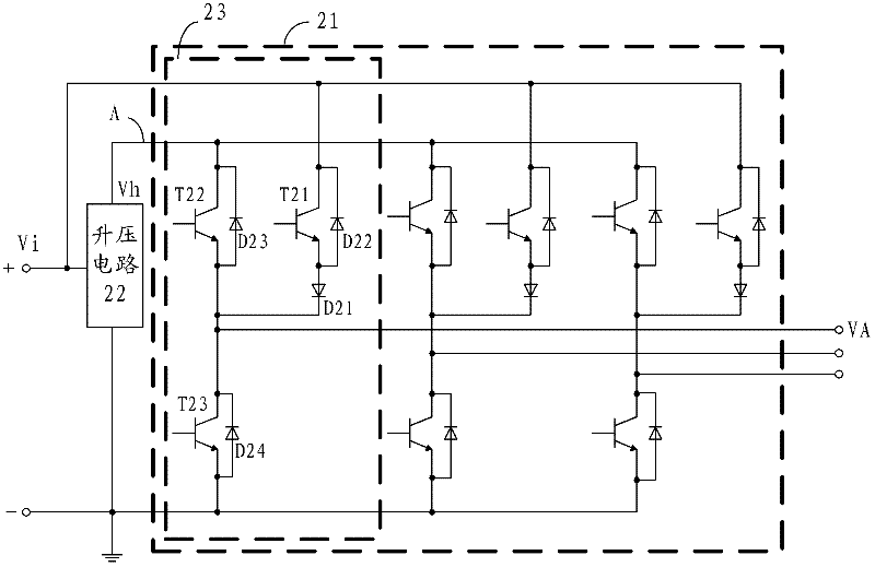
[0025] This embodiment provides an inverter device for converting DC power into AC power so as to provide AC power to loads such as power grids and motors. Such as figure 2 As shown, the inverter device has the following structure.

[0026] The inverter device includes: a bridge inverter 21 and a boost circuit 22, where the bridge inverter includes at least one bridge arm, figure 2 The bridge inverter shown has three bridge arms. Each bridge arm has the same structure and can output three-phase AC electric energy. Of course, the number of bridge arms is not limited to this. The bridge arms can be increased or decreased according to the demand of the load. The number of phases in order to increase or decrease the number of AC power phases. The structure of the at least one bridge arm is described below by taking the bridge arm 23 in the dashed frame as an example.

[0027] The bridge arm 23 includes: first to third power switch tubes (T21, T22, and T23) and a fi...

Example Embodiment

[0074] Example 2

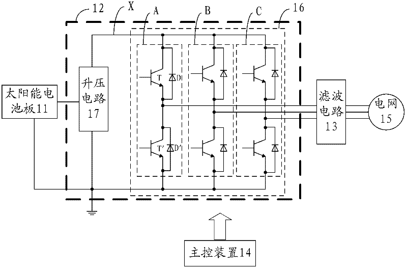
[0075] This embodiment provides a solar photovoltaic grid-connected system, such as Picture 10 As shown, the system includes: a solar panel 101, an inverter device 102 provided in Embodiment 1, a filter circuit 103, a main control device 104, and a power grid 105. The inverter device 102 is used to convert the DC power provided by the solar panel 101 into AC power through the control of the main control device 10, and is connected to the inverter device 102 and the power grid 105 The filtering by the filter circuit 103 transmits the AC power to the power grid 105. The specific circuit structure and working principle of the inverter device 102 have been described in detail in Embodiment 1, and will not be repeated here.

[0076] In this embodiment, since the inverter device provided in embodiment 1 is used, the efficiency of the solar photovoltaic grid-connected system can be significantly improved.


PUM


Abstract

The embodiment of the invention discloses an inverting device and a solar PV (Photovoltaic) grid-connected system applying the same, relates to the technical field of solar PV power generation, and solves the problems that in the existing inverting device, the energy consumption of a boosted circuit is higher, and the switching loss of an inverter is higher. In the embodiment of the invention, when the voltage of a direct-current power supply which is used for supplying power for the inverting device is lower, direct-current electricity can be simultaneously and directly supplied for the inverter in the inverting device through the boosted circuit and the direct-current power supply, thus the inverter can work in an inverting mode of three electric levels, not only can the energy consumption of the boosted circuit be reduced, but also the switching loss of the inverter can be reduced, and the efficiency of the whole system can be obviously increased when the inverting device is applied to a solar PV grid-connected system.

Description

technical field [0001] The invention relates to the technical field of solar photovoltaic power generation, in particular to an inverter device and a solar photovoltaic grid-connected system using the same. Background technique [0002] With the depletion of conventional energy and increasingly serious environmental problems, solar photovoltaic power generation, as an emerging clean energy industry, is developing very rapidly, with an annual growth rate of 30%. [0003] The inverter device is a bridge connecting solar photovoltaic power generation to the grid, and is one of the necessary equipment in the grid-connected solar photovoltaic power generation system. It is used to convert the direct current generated by the solar cells into the alternating current required by the grid. [0004] figure 1 The structure of the grid-connected solar photovoltaic power generation system used in the prior art is shown. The system includes: a solar panel 11 , an inverter device 12 , a ...

Claims


Application Information

Patent Timeline
IPC IPC(8): H02M7/5387H02M3/155H02J3/38
CPCH02M7/48H02M7/483Y02E10/56H02M7/5387H02M7/487Y02E10/563H02M2001/007H02J3/383H02J3/00H02J3/38H02M3/155H02M7/5388H02M3/158H02J2300/24H02J3/381H02M1/007
Inventor 李泉
Owner HUAWEI DIGITAL POWER TECH CO LTD
Why Eureka
Try Eureka