High-flow pressure-compensated drip irrigation emitter

A pressure compensation and irrigation technology, applied in the direction of spray device, spray device, etc., can solve the problems of large water demand and large terrain slope, and achieve the effect of large water demand, good pressure compensation performance and cost reduction

Inactive Publication Date: 2014-05-14
NORTHWEST A & F UNIV
View PDF9 Cites 2 Cited by
  • Summary
  • Abstract
  • Description
  • Claims
  • Application Information

AI Technical Summary

Problems solved by technology

[0005] Aiming at the problems of large terrain slope and large water demand in the irrigation of economic forests in mountainous areas, the purpose of the present invention is to provide a large flow pressure compensation type drip irrigation emitter. Combination of pressure compensation function, extrapolation and capillary, especially suitable for irrigation of species in mountainous economic forests and other areas with large water demand

Method used


Image

  • High-flow pressure-compensated drip irrigation emitter
  • High-flow pressure-compensated drip irrigation emitter
  • High-flow pressure-compensated drip irrigation emitter

Examples


Embodiment Construction

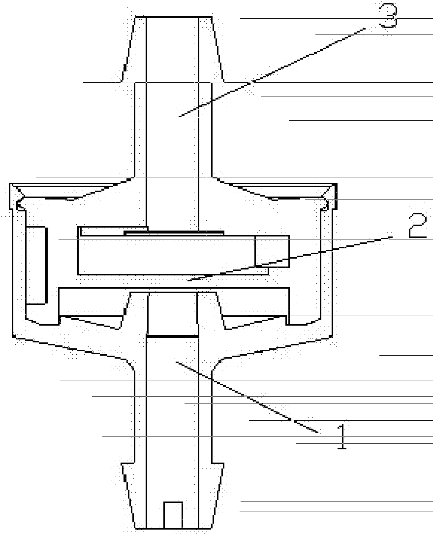
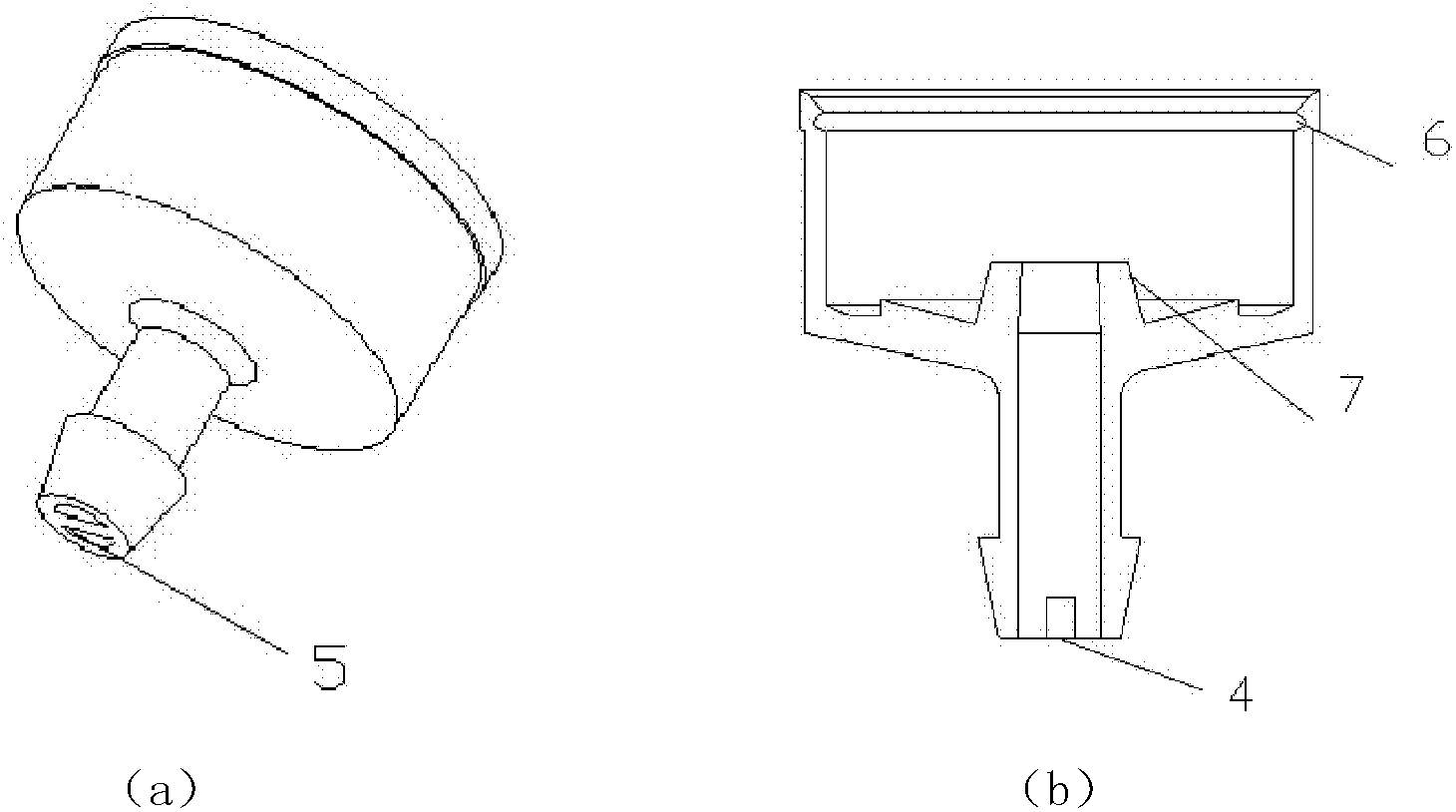
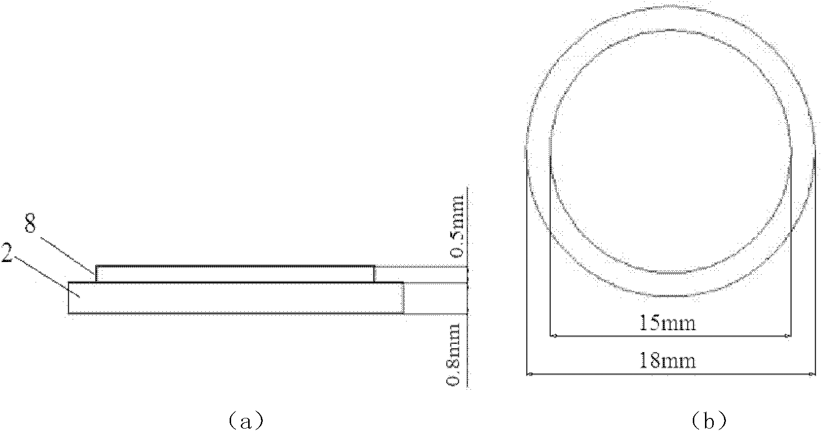
[0022] see figure 1 , the present embodiment provides a large-flow pressure-compensated drip irrigation emitter. The buried pressure-compensated spring root irrigation emitter is a combined structure, including a cavity 1, a pressure compensation gasket 2 and a base 3, and the three are cavity 1, pressure compensation gasket 2, and base 3 according to the order of water discharge. Seat 3. The cavity 1 is closely combined with the base 3 through the slot. The pressure compensating gasket 2 is located on the internal step structure of the base 3 . Matching with the step structure inside the base 3 ensures that the pressure compensating gasket 2 is fixed between the cavity 1 and the base 3 . The upper part of the pressure compensation gasket is the water inlet of the cavity 1, and the lower part is the water outlet of the base 3. When the upper part of the pressure compensation gasket 2 is under pressure, it is sunken, so that the emitter has different water outlet areas under...


PUM


Abstract

The invention discloses a high-flow pressure-compensated drip irrigation emitter, which is of a combined structure comprising a cavity, a pressure-compensated gasket and a base, wherein the emitter is connected with a tubular billet in an inserted manner. A water inlet and a filter screen are arranged on the cavity, a water outlet is positioned on the base, a labyrinth channel is attached onto the base, and the gasket is arranged between the cavity and the base. The working principle of the emitter includes that water flow enters the cavity of the emitter from a filter window of the water inlet of the emitter, flows through the upper surface of the gasket, enters the labyrinth channel through an inlet of the labyrinth channel, enters the base on the lower portion of the gasket through an outlet of the labyrinth channel to reach the water outlet after preliminary energy dissipation of the labyrinth channel, and a water outlet section of the lower portion of the pressure-compensated gasket is correspondingly changed along with constantly changing pressure, so that the flow rate of the emitter is changed.

Description

technical field [0001] The invention belongs to the technical field of agricultural economic forest irrigation in arid areas, and in particular relates to a large-flow pressure-compensated drip irrigation sprinkler, which is suitable for solving the economic forest irrigation problem. Background technique [0002] Micro-irrigation is currently the most water-saving irrigation technology. It is adopted by different crops in different regions. According to the water requirements and irrigation systems of different crops, the development of corresponding irrigators is the demand for the development of micro-irrigation. [0003] At present, there are three problems in the irrigation of mountain economic forests: one is that the uniformity of irrigation is difficult to ensure due to the large height difference in the mountains; For large perennial fruit trees, such an emitter cannot well meet the water demand of the fruit tree during the vigorous growth period, thus becoming a ma...

Claims


Application Information

Patent Timeline
Patent Type & Authority Patents(China)
IPC IPC(8): B05B1/30B05B1/14
Inventor 朱德兰李令媛张林牛文鹏陈俊英力波王剑巩兴辉
Owner NORTHWEST A & F UNIV
Why Eureka
Try Eureka