Material-receiving system for band saw gear milling machine

A technology for a tooth milling machine and a saw belt is applied in the field of the material receiving system of the saw belt milling machine, which can solve the problems of difficult cutting, low material collection efficiency, bending of the saw belt, etc., so as to improve the quality of milling teeth and improve labor efficiency. , The effect of easy feeding process

Active Publication Date: 2012-07-04
BICHAMP CUTTING TECH (HUNAN) CO LTD
View PDF5 Cites 6 Cited by
  • Summary
  • Abstract
  • Description
  • Claims
  • Application Information

AI Technical Summary

Problems solved by technology

[0003] (1) The traditional material receiving method adopts the tower-type spiral ascending and layered material receiving method, which cannot realize automatic material receiving, and manual operation is required to collect materials every once in a while;
[0004] (2) The traditional way of receiving tower, because the saw band spirally rotates around the receiving tower, and multiple saw bands are in contact with each other, causing serious bending of the saw band, which is easy to cause tooth tip damage and scratches, which seriously affects the saw band milling. tooth quality;
[0005] (3) The efficiency of receiving materials in the traditional way is low, and each milling machine needs a special person to be i...

Method used


Image

  • Material-receiving system for band saw gear milling machine
  • Material-receiving system for band saw gear milling machine
  • Material-receiving system for band saw gear milling machine

Examples


Embodiment Construction

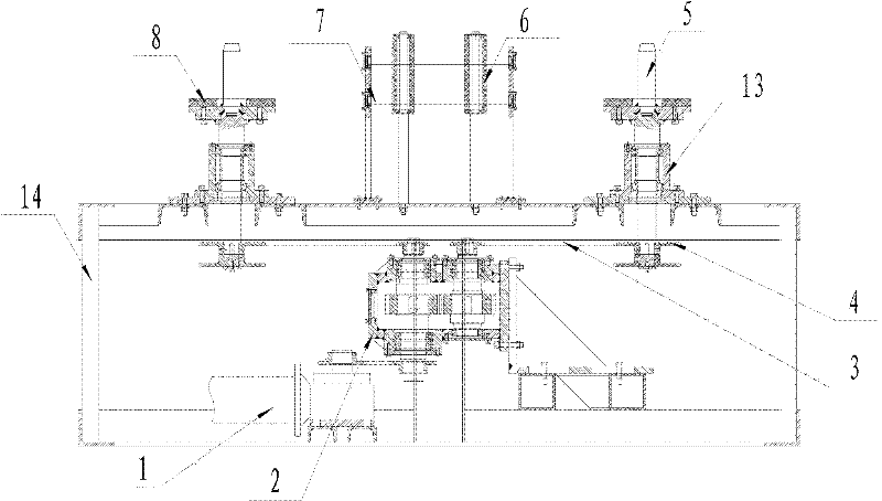
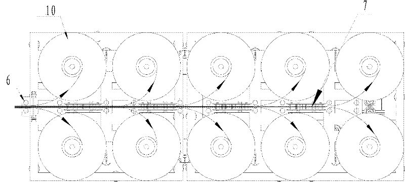
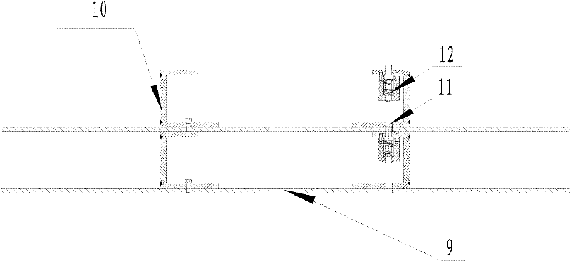
[0024] Such as Figure 1-Figure 3 As shown, a material receiving system of a saw band milling machine includes a base support 14 and a receiving tray 10, the base support 14 is equipped with a motor 1, and a plurality of receiving trays 10 are arranged on both sides of the top of the base support 14 to form a Parallel and symmetrical two rows of receiving trays, the two rows of receiving trays are located at the same height position to form a layer of receiving trays, between the two rows of receiving trays 10 are provided with a supporting mechanism 7 for supporting the saw band and a limit saw The blocking wheel 6 with the transmission direction; the center of each receiving tray 10 is provided with a positioning hole 9, and the receiving tray 10 is a layer or a multilayer placed in parallel up and down and is provided with a positioning shaft 5 to pass through each layer of receiving trays vertically. The positioning hole 9 of the charging tray 10, the bottom of each positi...


PUM


Abstract

The invention relates to a material-receiving system for a band saw gear milling machine. A plurality of material-receiving plates are arrayed on two sides at the top of a base bracket, so as to form two rows of material-receiving plates in parallel; the two rows of material-receiving plates are located at same altitude, thereby forming a layer of material-receiving plates; a material supporting mechanism and a material stopping wheel are arranged between the two rows of material-receiving plates; the material supporting mechanism is used for supporting a band saw; the material stopping wheelis used for limiting a transmission direction of the band saw; one layer or multiple vertical parallel layers of the material-receiving plates are arranged; positioning holes, by which positioning shafts vertically pass through each layer of the material-receiving plates, are formed; the bottom of each of the positioning shafts is connected with a material-receiving slewing mechanism; a constant speed gear box is arranged on the base bracket between the two rows of material-receiving plates; a motor output shaft is connected with an input shaft of the constant speed gear box; and two output shafts of the gear box are respectively connected with the material-receiving slewing mechanisms on two sides of the constant speed gear box through a conveying mechanism. In the material-receiving system for the band saw gear milling machine provided by the invention, saw bands are directly divided into upper and lower two layers which do not interfere and contact each other; the quality accidents, such as bending, bumping, and the like, of the saw bands are avoided while the materials are received; and the quality level during a band saw gear milling process is increased.

Description

technical field [0001] The invention relates to a material receiving system of a saw band milling machine. Background technique [0002] The existing material receiving mechanism of the saw band milling machine mainly relies on manual material receiving, and its shortcomings are mainly reflected in the following aspects: [0003] (1) The traditional material receiving method adopts the tower-type spiral ascending and layered material receiving method, which cannot realize automatic material receiving, and manual operation is required to collect materials every once in a while; [0004] (2) The traditional way of receiving tower, because the saw band spirally rotates around the receiving tower, and multiple saw bands are in contact with each other, causing serious bending of the saw band, which is easy to cause tooth tip damage and scratches, which seriously affects the saw band milling. tooth quality; [0005] (3) The efficiency of receiving materials in the traditional wa...

Claims


Application Information

Patent Timeline
IPC IPC(8): B23D65/04B23Q7/00
Inventor 李栋梁
Owner BICHAMP CUTTING TECH (HUNAN) CO LTD
Why Eureka
Try Eureka