Cooling fan compression joint device

A crimping device and cooling fan technology, which is applied in metal processing, metal processing equipment, manufacturing tools, etc., can solve the problems of unstable pressing process, insufficient positioning accuracy of the lower fixture, and insufficient guiding accuracy of the lower fixture, so as to reduce rework Rate and scrap rate, reduce press-fitting alarms, and ensure the effect of positioning accuracy

Active Publication Date: 2014-02-12
SHANGHAI BROSE AUTOMOTIVE COMPONENTS
View PDF8 Cites 0 Cited by
  • Summary
  • Abstract
  • Description
  • Claims
  • Application Information

AI Technical Summary

Problems solved by technology

[0007] One is that the guiding accuracy of the lower fixture is guaranteed by the guide column on one side. In long-term use, the guide column will be offset due to wear. Due to the lack of necessary testing tools, it is impossible to determine the offset of the guide column. The direction and the specific offset cannot be corrected in time, resulting in insufficient guidance accuracy when the lower fixture goes down;
[0008] The second is that the positioning accuracy of the lower fixture is determined on the support plate through the locking bolt, and the support plate is determined on the horizontal base through the guide column. When the guide column is worn, the support plate will also shift and the positioning accuracy of the lower fixture will be insufficient. ;
[0009] The third is that different types of motors and cooling fans require different positioning of the lower fixture. After replacing the lower fixture, the alignment accuracy of the new lower fixture and the upper guide pin cannot be determined due to the lack of necessary testing tools and means.
[0010] Because the existing tooling scheme fails to fully consider the above process requirements, it is easy to cause uneven fit interference during the press-fit process, unstable press-fit process, excessive press-in force, and press-fit alarm rate of more than 10% during the production process. Caused problems such as high press-fit cost of cooling fan and motor, low efficiency, and time-consuming

Method used


Image

  • Cooling fan compression joint device
  • Cooling fan compression joint device
  • Cooling fan compression joint device

Examples


Embodiment Construction

[0035] The present invention will be further described below in conjunction with accompanying drawing.

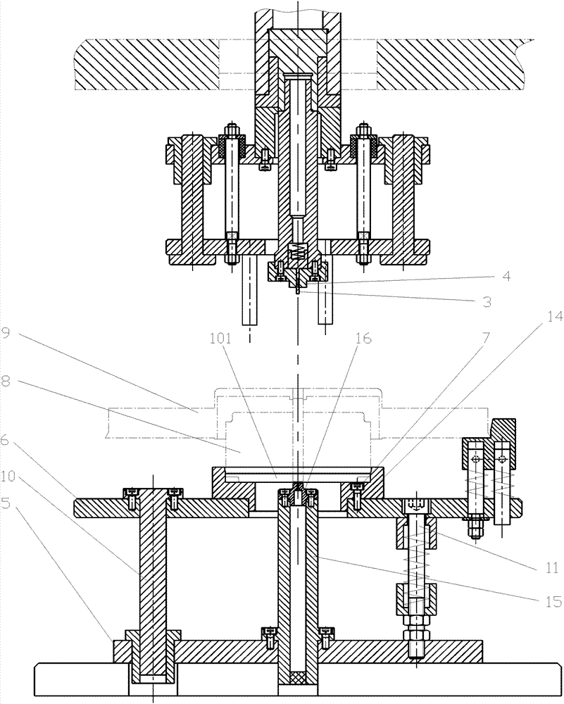
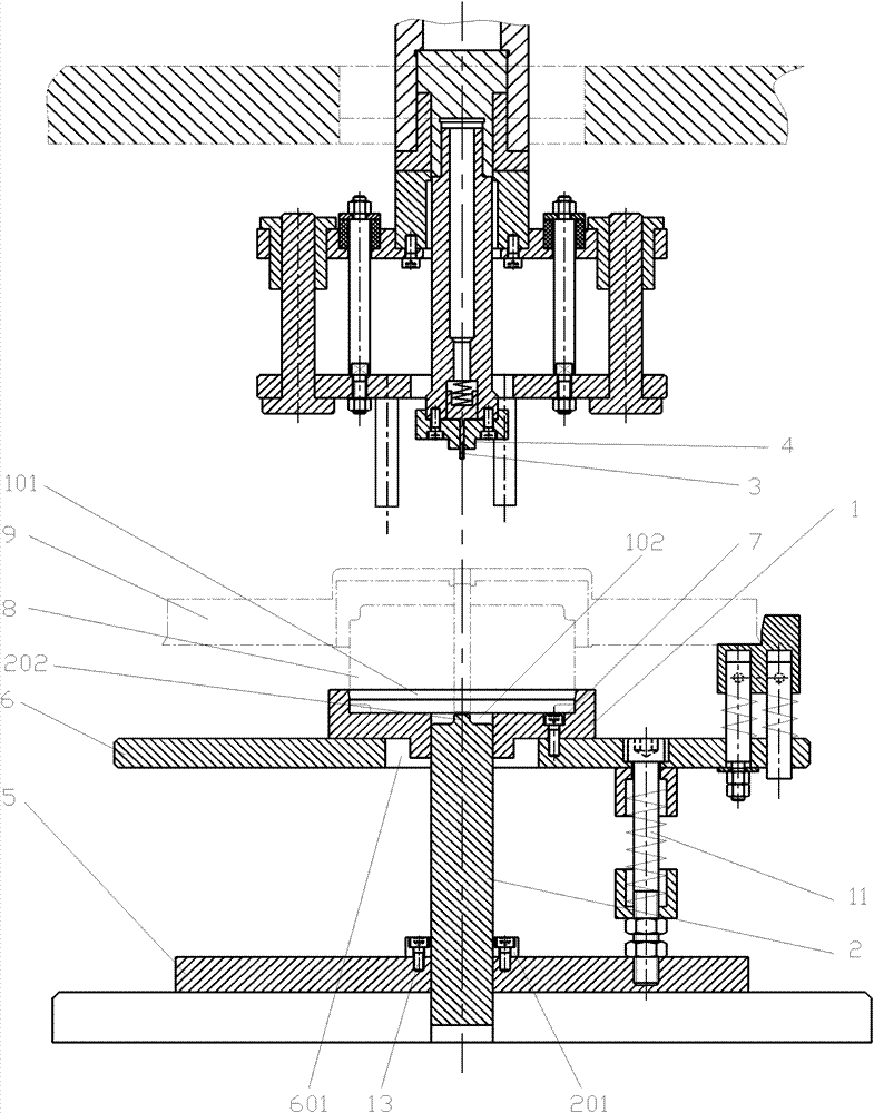
[0036] The currently used crimping device is to arrange a support plate 6 in parallel on the top of the horizontal base 5, the center of the support plate 6 is provided with an installation hole, and the existing lower clamp 14 in the shape of a stepped disc is arranged above the support plate 6. The small end extends into the installation hole and fits with the installation hole. The large end rests on the support plate 6 and is fixed with the support plate 6 by the locking bolt 7. The large end is provided with a motor positioning cavity 101, and the center of the small end is provided with a through hole. , the through hole communicates with the motor positioning cavity, a support rod 15 is arranged in the through hole, the outer diameter of the support rod 15 is smaller than the inner diameter of the through hole, the upper end of the support rod 15 is fixed with a suppo...


PUM


Abstract

The invention relates to an improved structure of a cooling fan compression joint device. A liftable supporting plate is arranged in parallel above a horizontal base. The center of the supporting plate is provided with a mounting hole. A lower clamp which is of a step disk shape is arranged above the supporting plate. The small end of the lower clamp extends into the mounting hole. The outer diameter of the small end of the lower clamp is less than the aperture of the mounting hole on the supporting plate. The big end of the lower clamp is provided with a motor positioning cavity. The center of the small end of the lower clamp is provided with a through hole. The through hole is communicated with the motor positioning cavity. A vertical ejector rod is arranged in the through hole of the lower clamp. The ejector rod is in clearance fit with the through hole. The center of the end face of the upper end of the ejector rod protrudes to form an ejector head. An upper guide pin capable of vertically lifting and descending is coaxially arranged above the lower clamp. A device is provided with a vertical centering rod. The upper and lower end faces of the vertical centering rod are respectively provided with coaxial centering holes. The coaxiality of the upper guide pin and the lower clamp is detected before press mounting by utilizing the centering rod, so that the press mounting process is ensured stable, the interference is uniform, the pressure is reduced, the press mounting alarm is reduced and the rework rate and the rejection rate are reduced, and thus, the cost is reduced.

Description

technical field [0001] The invention relates to a crimping device, in particular to the crimping of motors and cooling fans on automobiles. Background technique [0002] The assembly of the cooling fan and the motor on the car is an interference fit connection, the minimum interference is 0.008mm, and the maximum interference is 0.028mm. The press-fitting process of the cooling fan and the motor is done by a crimping device. [0003] The currently used crimping device is to arrange a support plate in parallel above the horizontal base. A mounting hole is opened in the center of the support plate. A stepped disc-shaped lower clamp is arranged above the support plate. The small end of the lower clamp extends into the mounting hole. The gaps of the holes are matched, the big end rests on the support plate, and is fixed with the support plate by locking bolts, the big end is provided with a motor positioning cavity, and the center of the small end is provided with a through hol...

Claims


Application Information

Patent Timeline
Patent Type & Authority Patents(China)
IPC IPC(8): B23P19/02
Inventor 赵春辉叶志维
Owner SHANGHAI BROSE AUTOMOTIVE COMPONENTS
Why Eureka
Try Eureka