Clamp structure for C-shaped ferrite magnetic core

A ferrite core and font technology, which is applied in the field of tooling and fixtures, can solve the problems of volume expansion, affecting power, and no C-shaped ferrite cores, etc., and achieves the effect of concise structure and convenient operation.

Inactive Publication Date: 2012-07-04
CHANGSHU XINLI MAGNETIC IND
View PDF10 Cites 12 Cited by
  • Summary
  • Abstract
  • Description
  • Claims
  • Application Information

AI Technical Summary

Problems solved by technology

[0004] The following technical problems exist in any one of the above three methods for obtaining the positioning reference plane: as far as the first method forms a concave platform at the top of the arc, since the cross-section of the C-shaped ferrite core is reduced, Therefore, it directly affects the power; as far as the second method is to form a convex platform at the top of the arc, because the volume is enlarged, it is difficult to match with electronic and electrical products or lighting equipment during use; In terms of pre-grinding the positioning datum plane at the top, there is not only the deficiency of the first method, but also a sharp corner will be formed at the edge of the datum plane, which will damage the coil when winding the coil
It is based on this factor that there is no corresponding technical revelation suitable for effectively holding back the aforementioned C-shaped ferrite core in the current published patents and non-patent literature.

Method used


Image

  • Clamp structure for C-shaped ferrite magnetic core
  • Clamp structure for C-shaped ferrite magnetic core

Examples


Embodiment

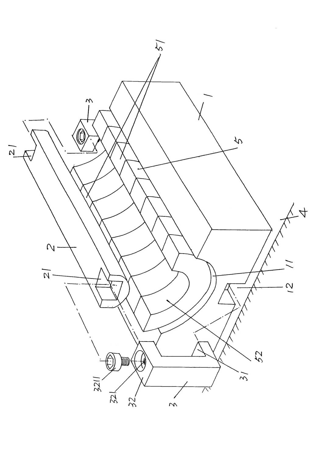
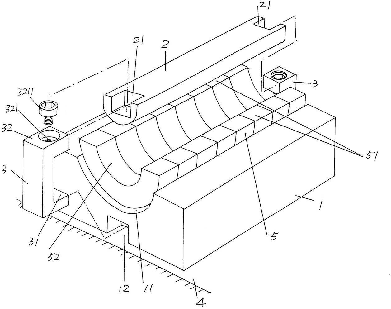
[0017] Please see figure 1 , gives a base 1 whose length does not need to be deliberately limited, in order to facilitate the understanding of the public in figure 1 In the center, the grinder table 4 of the grinder and the C-shaped ferrite core 5 used for grinding are shown. The surface of the base 1 facing upward in the use state, that is, the surface of the side facing the ferrite core 5, is formed from one end to the other end in the length direction (also called the long side direction) of the base 1, that is, A C-shaped cavity 11 from the left end to the right end of the position shown in the figure, the depth of this C-shaped cavity 11 is smaller than the height of the ferrite core 5, so that the two ends of the ferrite core 5 protrude from the C-shaped cavity 11. Grinding the end face 51 of the ferrite core 5 with a grinder of a grinding machine. In the state of use, the base 1 faces downwards, that is, the two ends of the side facing the aforementioned grinding...


PUM


Abstract

A clamp structure for a C-shaped ferrite magnetic core belongs to the technical field of tooling clamps and comprises a base, a press bar and a pair of clamping pins. A C-shaped cavity penetrating from one end of the base in the length direction to the other end of the base is formed on the upward surface of one side of the base in the use state, a hook plate containing cavity is respectively arranged on end portions of two ends of a downward side of the base in the use state, and the hook plate containing cavity is located in the middle position of the base in the width direction. The press bar is matched with the C-shaped cavity, and a concave cavity is respectively formed at two ends of the press bar. One end of the pair of clamping pins is matched with the hook plate containing cavity, and the other end of the pair of clamping pins is matched with the concave cavities. The clamp structure for the C-shaped ferrite magnetic core has the advantages of being capable of not only ensuring power of the C-shaped ferrite magnetic core and assembling effect during use but also avoiding coil damage during coil winding, and being compact in structure and convenient to operate.

Description

technical field [0001] The invention belongs to the technical field of fixtures, and in particular relates to a fixture structure for processing a C-shaped ferrite core. Background technique [0002] The aforementioned C-shaped ferrite cores are not limited to be used in electrical and electronic products, lighting equipment and the like. Usually, it is necessary to grind the C-shaped ferrite core, and the positioning reference plane needs to be determined during the grinding process, and the positioning must also be ensured reliably, otherwise the grinding process effect will be affected, or even scrapped. [0003] Due to the special shape and relatively small size of the C-shaped ferrite core, it is very difficult to locate it in the subsequent grinding process. For this, the industry usually focuses on changing the shape, such as for pressing the C-shaped ferrite core. The mold of the ferrite core blank is modified so that the pressed C-shaped ferrite core blank forms a ...

Claims


Application Information

Patent Timeline
Patent Type & Authority Applications(China)
IPC IPC(8): B24B41/06H01F41/02
Inventor 陆栋明胡磊王伟
Owner CHANGSHU XINLI MAGNETIC IND
Why Eureka
Try Eureka