Power tool

A power tool and drive shaft technology, applied in the field of power tools, can solve problems such as large sudden change of torque and impact, and achieve the effects of simple and compact structure, convenient use, labor saving and cost reduction

Active Publication Date: 2012-07-04
NANJING CHERVON IND
View PDF7 Cites 18 Cited by
  • Summary
  • Abstract
  • Description
  • Claims
  • Application Information

AI Technical Summary

Problems solved by technology

[0003] Although this clamping device can basically clamp the working element to the output shaft of the hand tool without auxiliary tools, this clamping device is only suitable for clamping the working element that is driven by rotation, if the working element is driven by the vibration device drive so that the working element oscillates back and forth along the longitudinal axis of the output shaft, this results in large abrupt torques in both directions of rotation and with extreme shocks, which cannot be ensured by known clamping devices Clamp the working element fully and firmly

Method used


Image

  • Power tool
  • Power tool
  • Power tool

Examples


Embodiment Construction

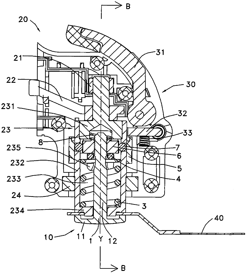
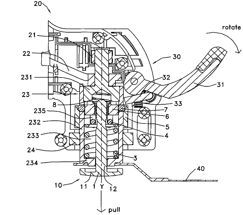
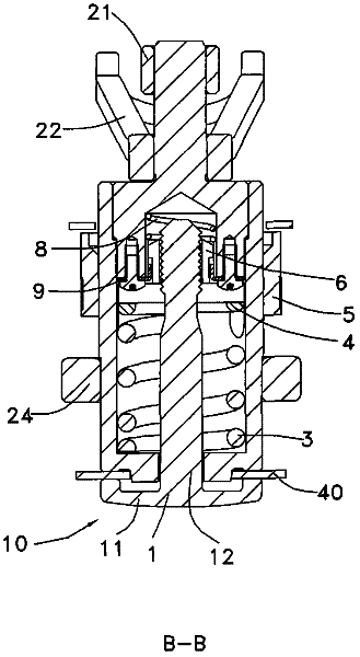
[0032] Such as Figure 1 to Figure 4 As shown, the present invention is preferably described as a power tool 20 that drives the working element 40 in an oscillating manner. The power drive shaft 23 of the power tool 20 is supported by bearings 21, 24 and rotates around its axis Y under the action of the vibrating support 22. Small yaw angle and high-frequency reciprocating swing, the drive shaft 23 is configured to support the journal 231 and the hollow shaft 232, the vibration support 22 is interference-fitted on the support journal 231, and the support journal 231 and the hollow shaft 232 interference press fit, support journal 231 and hollow mandrel 232 are surrounded by cavity 233, the shaft end 234 of driving shaft 23 is provided with the protrusion that prevents working element 40 from rotating, is connected on the driving shaft 23 and is used for working element 40 The clamping device 10 is quickly clamped to the shaft end 234 .

[0033] The clamping device 10 comprise...


PUM


Abstract

The invention provides a power tool, which comprises a driving shaft, a fastening element and a locking component, wherein the driving shaft drives a working element; the fastening element fastens the working element to the driving shaft and has an extended shaft which may be inserted into the driving shaft; the locking component locks the extended shaft in the driving shaft and comprises a locking piece and a moving piece, the locking piece has a locking position for locking the extended shaft and a release position for releasing the extended shaft, the fastening element moves toward the end part of the driving shaft through an elastic element in the locking position, the moving piece is arranged outside the driving shaft has first and second parts which can be directly or indirectly matched with the locking piece, and the radical distance from the first part to the shaft center of the driving shaft is unequal to the distance from the second part to the shaft center of the driving shaft. The power tool provided by the invention acts quickly to clamp and has a compact structure; and by arranging the moving piece outside the driving shaft, the arm of force of a wrench is prolonged, and labor can be saved.

Description

technical field [0001] The present invention relates to a power tool comprising an output shaft for driving the tool and a fastener for clamping a working element to the end of the output shaft, and a fastener for making the fastener A moving device that moves between a released position and a clamped position, in which the fastener can be removed from the output shaft by disengaging from the moving device, whereas in the clamped position, the fastener is locked by the moving device The joint and the elastic element work together to support the end of the output shaft so that the working element is firmly clamped. Background technique [0002] Known from US006569001B2 is a power tool with a quick clamping device, the hand tool is an angle grinder, the angle grinder is equipped with a hollow output shaft, and a hollow shaft is installed in the hollow shaft. Clamping device movable between a clamped position and a released position, the clamping device comprises a clamping fl...

Claims


Application Information

Patent Timeline
Patent Type & Authority Applications(China)
IPC IPC(8): B25F5/00
CPCB23D61/006B27B5/32B24B45/006B24B23/022B23D61/10Y10T83/7045Y10T83/9457Y10T279/32Y10T279/33
Inventor 周红陶
Owner NANJING CHERVON IND
Why Eureka
Try Eureka