Current collector

A current collector and boot removal technology, which is applied in the field of current collectors, can solve the problems of electric shock, inability to remove boots, and dangers of operators, and achieve the effects of high operating safety, simple structure, and reasonable design

Inactive Publication Date: 2012-07-04
陈革
View PDF6 Cites 10 Cited by
  • Summary
  • Abstract
  • Description
  • Claims
  • Application Information

AI Technical Summary

Problems solved by technology

Its disadvantages: Although this method of taking off the boots is simple in structure, it needs to go under the vehicle and operate on the ground near the power supply rail. Because the power supply rail carries DC750V or even DC1500V high-voltage direct current, the operator has the risk of electric shock. At the same time, due to the limitation of space, it is impossible to take off the boots on the platform and other places

Method used


Image

  • Current collector
  • Current collector
  • Current collector

Examples


Embodiment 1

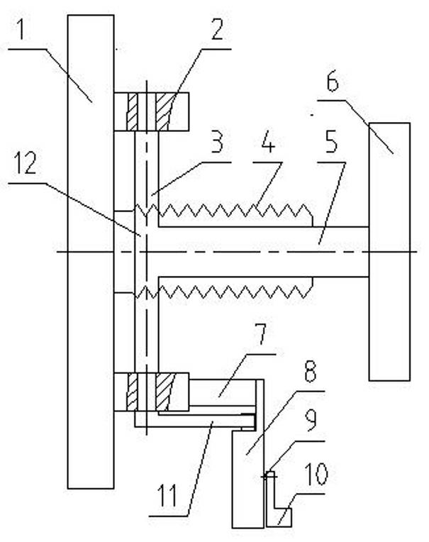
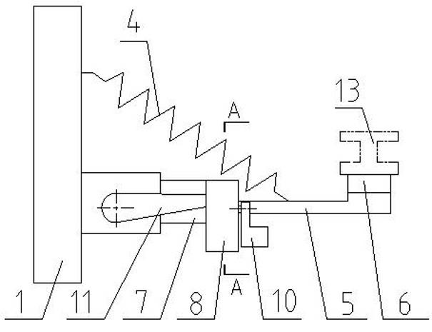
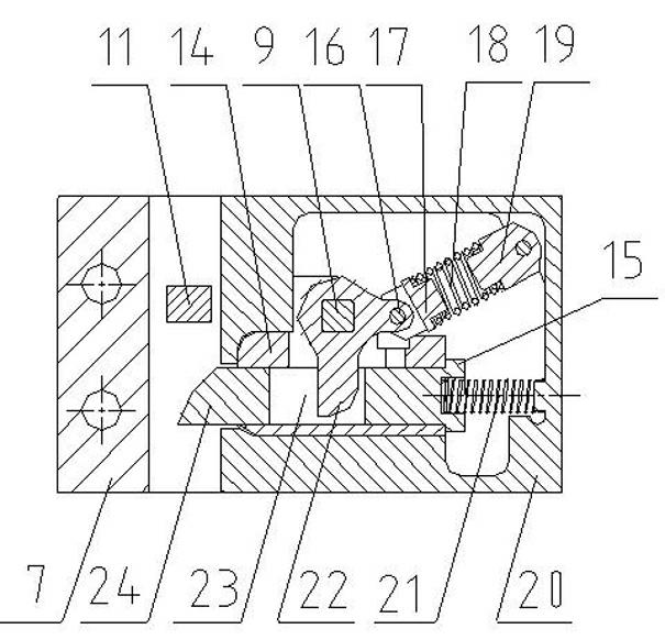
[0025] Including current receiver main body 1, swing lever mechanism 12, sliding shoe 6 and cables; said swing lever mechanism 12 includes swing lever rotating shaft 3 and its support 2, main spring 4, sliding shoe swing lever 5, shoe removal locking device 8 , Sliding shoe auxiliary rod 11; the sliding shoe swing rod 5 and the sliding shoe auxiliary rod 11 are parallel to each other, and are all perpendicular to the swing rod shaft 3; the shoe removal locking device 8 is installed on the flow receiving The main body 1 of the shoe, the tail of the auxiliary shoe lever 11 falls into the boot-off locking device 8; the boot-off locking device 8 includes a boot-off locking device casing 20, a deadbolt 24, a deadbolt spring 21, a shift fork Axis 9, shift fork 22; Dead bolt spring 21 is installed in dead bolt 24 afterbody; The tongue body of dead bolt 24 is provided with shift fork groove 23, and the head of shift fork 22 falls in shift fork groove 23; Shift fork 22 is installed in s...

Embodiment 2

[0027] On the basis of Embodiment 1, a deadbolt sliding seat 14 is installed between the deadbolt 24 and the housing 20 of the boot removal locking device. Installing the dead bolt sliding seat 14 is mainly from the considerations of technology, maintenance and production cost.

Embodiment 3-4

[0029] On the basis of Embodiment 1, the tail of the lock tongue 24 is provided with a limiting boss 15 to limit the protruding length of the lock tongue 24 .

[0030] Working principle, take embodiment 1 as an example to illustrate:

[0031] (1) Take off the boots: If an insulating rope is used to pull the sliding boot swing lever 5, the boots off 6 are separated from the power supply rail 13, and the tail of the auxiliary lever 11 of the sliding boots rotates synchronously. Figure 3-4 Turn clockwise as shown, the head of the shift fork 22 falling into the shift fork groove 23 pushes against the inner wall of the shift fork groove 23 near the dead bolt spring 21, forcing the dead bolt 24 to compress the dead bolt spring 21, and the head of the dead bolt 24 After the part retracts and enters the casing 20 of the boot-off locking device, the tail portion of the auxiliary shoe lever 11 continues to rotate to the bottom of the lock tongue 24, and then the fork control lever 10 i...


PUM


Abstract

The invention discloses a current collector. The current collector comprises a current collector main body and a swing rod mechanism, wherein the swing rod mechanism comprises a swing rod rotating shaft, a swing rod rotating shaft support, a main spring, a skid shoe swing rod, a shoe removal locking device and a skid shoe auxiliary rod; the skid shoe swing rod and the skid shoe swing rod are parallel mutually and vertical to the swing rod rotating shaft; the shoe removal locking device is mounted at the current collector main body, and the tail part of the skid shoe auxiliary rod falls into the shoe removal locking device; the shoe removal locking device comprises a shoe removal locking device enclosure, a locking dog, a locking dog spring, a shift fork shaft and a shift fork; a locking dog body is provided with a shift fork groove, and the head part of the shift fork falls into the shift fork groove; the shift fork is mounted on the shift fork shaft, the shift fork shaft is fixed in the shoe removal locking device enclosure, at least one end part of the shift fork shaft extends to the exterior of the shoe removal locking device enclosure, and a shift fork operating lever is mounted at the extending end; and a self-locking device is mounted at the tail part of the shift fork. Compared with the prior art, the current collector disclosed by the invention has the advantages of simple and reliable structure, more reasonable design, higher safety in operation, greater convenience and the like.

Description

technical field [0001] The invention relates to a current collector, in particular to a current collector suitable for receiving current on the third rail of urban rail transit vehicles. Background technique [0002] The current collector is a current receiving device installed on the bogie of urban rail transit vehicles. Through the sliding contact between the sliding shoes on the current collector and the ground power supply rail, the ground electric energy is guided to the train. When the current receiver is working normally, under the action of the spring force, the current receiver swing rod and the current receiver sliding shoe are pressed to the power supply rail (the third rail), so that the current receiver sliding shoe is in contact with the power supply rail. When the vehicle encounters a fault and needs to be inspected or overhauled, the current receiver needs to be disconnected from the power supply rail, and the current receiver sliding shoe is forcibly disenga...

Claims


Application Information

Patent Timeline
Patent Type & Authority Applications(China)
IPC IPC(8): B60L5/39
Inventor 陈革陈俊铭
Owner 陈革
Why Eureka
Try Eureka