Rear floor structure for a motor vehicle

A technology of bottom structure and automobile, applied in the directions of substructure, superstructure, superstructure sub-assembly, etc., can solve the problems affecting the durability and limitation of longitudinal force of longitudinal beams

Inactive Publication Date: 2012-07-04
GM GLOBAL TECH OPERATIONS LLC
View PDF0 Cites 6 Cited by
  • Summary
  • Abstract
  • Description
  • Claims
  • Application Information

AI Technical Summary

Problems solved by technology

The spacious wheel housings that provide room for the wheels and associated shock absorbers limit the space in the body that can be used for passenger cabin seats or as a luggage compartment
In addition, these wheel arches necessitate a significantly inwardly offset course of the longitudinal beams, which affects the durability of the longitudinal beams with respect to the longitudinal forces occurring in the event of a collision

Method used


Image

  • Rear floor structure for a motor vehicle
  • Rear floor structure for a motor vehicle
  • Rear floor structure for a motor vehicle

Examples


Embodiment Construction

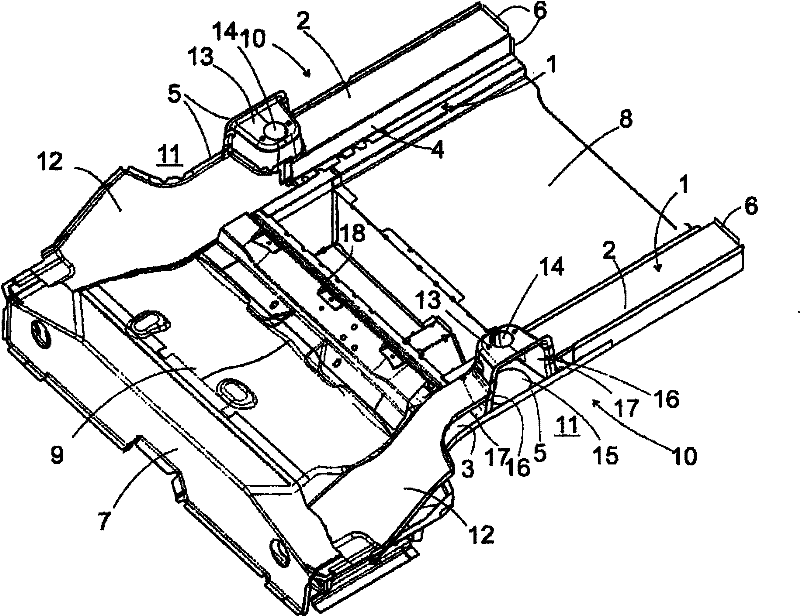
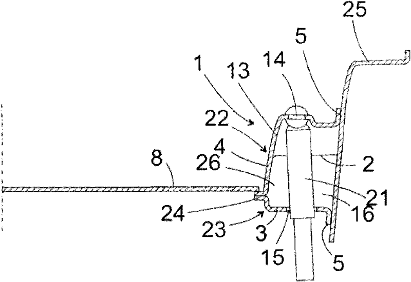
[0021] figure 1 A rear underbody structure for a motor vehicle is shown in perspective view. The side walls of the floor structure are formed by two longitudinal beams 1 . The two side members 1 are profiles with a hat-shaped cross-section that are each open towards the outside of the vehicle. image 3 As can be better seen in , the profile has a substantially horizontal upper wall 2, a lower wall 3, a side wall 4 connecting the walls 2, 3 and a flange forming a hat-shaped cross-section, like the side wall 4 A substantially vertical connecting piece 5 . figure 1 The side members 1 shown each have at their rear ends a flange 6 for fastening a bumper cross member (not shown). The cross member 7 connecting the front ends of the side members 1 to each other is located below the front edge of the rear seat cushions when the vehicle is installed and forms the rear wall of the footwell of the passengers in the rear seat. The rear floor 8 , the pan 35 and the front floor 9 fill th...


PUM


Abstract

A rear floor structure for a motor vehicle includes, but is not limited to two longitudinal girders extending between rear wheel houses. A downwardly open pocket for receiving a shock absorber is formed in each of the longitudinal girders.

Description

technical field [0001] The invention relates to the construction of a rear underbody structure for a motor vehicle, in particular an underbody structure for a coupe optimized with regard to its crash performance. Background technique [0002] The vehicle substructure usually comprises a lattice structure of side members and cross members, which can be assembled together or designed in one piece, for example as a cast part. The forces occurring in the direction of travel in the event of a crash must largely be absorbed and dissipated by the side members in order to prevent deformations of the cabin that threaten the safety of the passengers. The longitudinal beam rigidity required for this purpose should be achieved with the lowest possible weight, on the one hand for reasons of manufacturing costs and on the other hand for fuel-efficient operation of the vehicle. [0003] The more compact the body of a vehicle, the more difficult it is to meet the requirements for the side ...

Claims


Application Information

Patent Timeline
Patent Type & Authority Applications(China)
IPC IPC(8): B62D21/15B62D21/02
CPCB62D25/087B62D25/088B62D25/2027B60G15/068B60G2204/128B62D21/11
Inventor M·施沃茨J·赫尔伯特S·罗森普兰特J·弗里津格A·斯特恩J·西本尼克M·哈德D·埃利希W·索尔尼卡O·马热G·海姆S·奥利格希拉格
Owner GM GLOBAL TECH OPERATIONS LLC
Why Eureka
Try Eureka