Design method for multifunctional helicopter

A design method and technology of helicopters, applied in the direction of rotorcraft, motor vehicles, aircraft, etc., can solve the problems of increasing the total power consumption and weight of the whole machine, complexity, and bulky duct walls

Inactive Publication Date: 2012-07-04
周景荣
View PDF5 Cites 43 Cited by
  • Summary
  • Abstract
  • Description
  • Claims
  • Application Information

AI Technical Summary

Problems solved by technology

Its disadvantages are: the duct wall is too bulky, and the torsional moment and torque are too large and concentrated during the tilting and fixing process, which brings serious overweight problems to the design fuselage
Its disadvantage is that it needs a larger paddle disk solidity when it takes off and lands vertically and hovers in the air, which is beneficial to increase the paddle disk load
Its disadvantages are: too many and complicated functional mechanism designs, which increase the weight of this part and increase the cost of design and manufacturing
Its disadvantages are: a pair of empennage is needed to balance the counter torque of the rotor, which increases the total power consumption and weight of the whole machine
Although the flight speed and range of the helicopter have been improved, its load capacity is far inferior to that of the rotor helicopter when it takes off vertically.

Method used


Image

  • Design method for multifunctional helicopter
  • Design method for multifunctional helicopter
  • Design method for multifunctional helicopter

Examples


Embodiment Construction

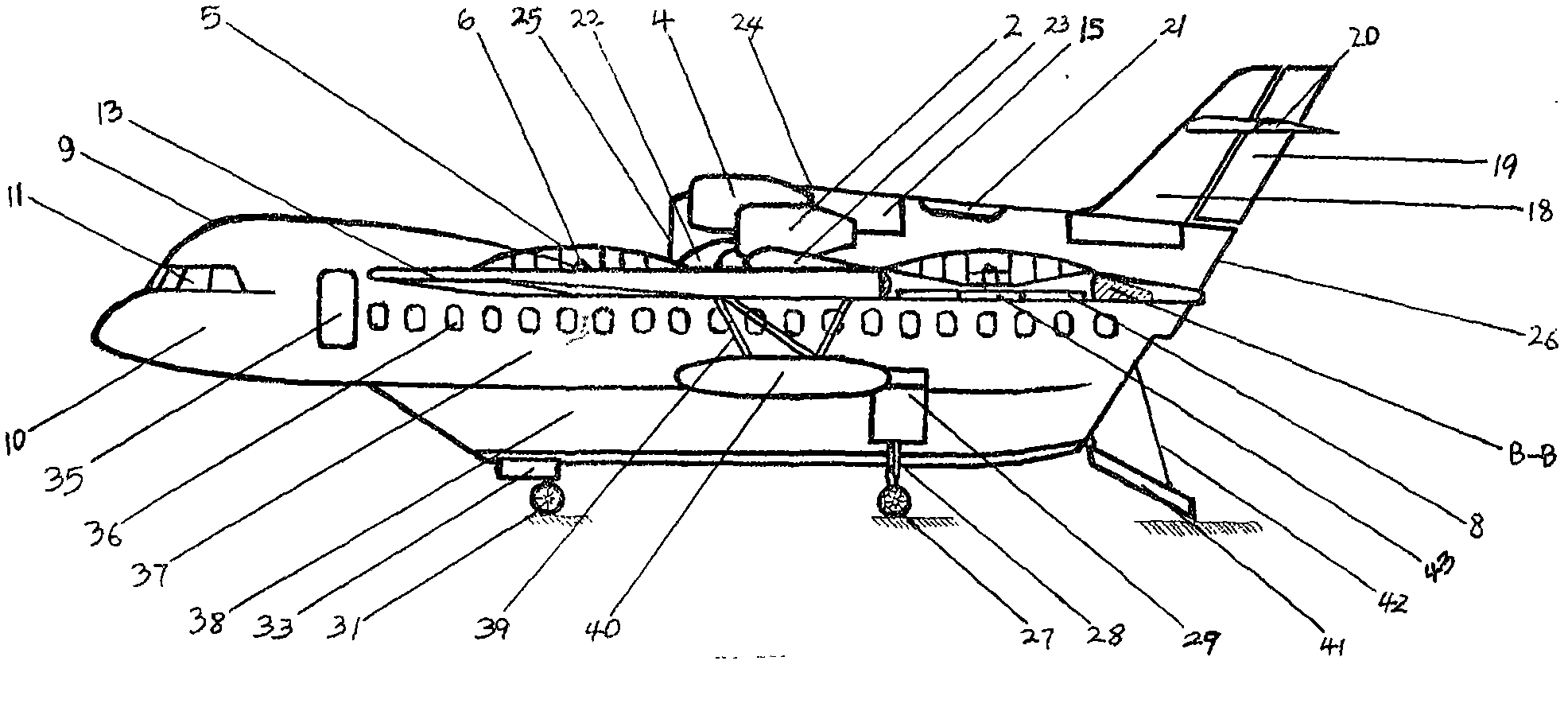
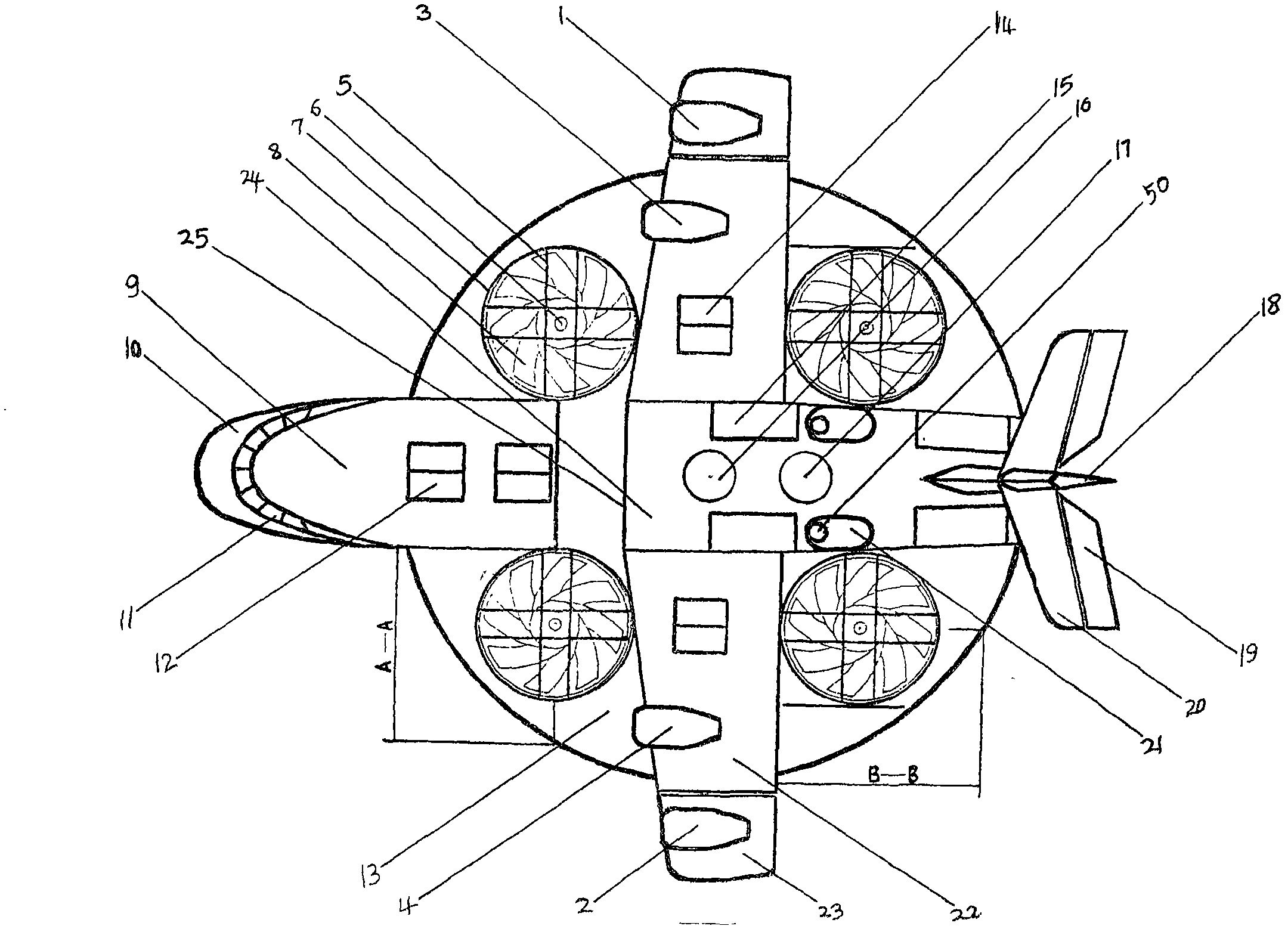
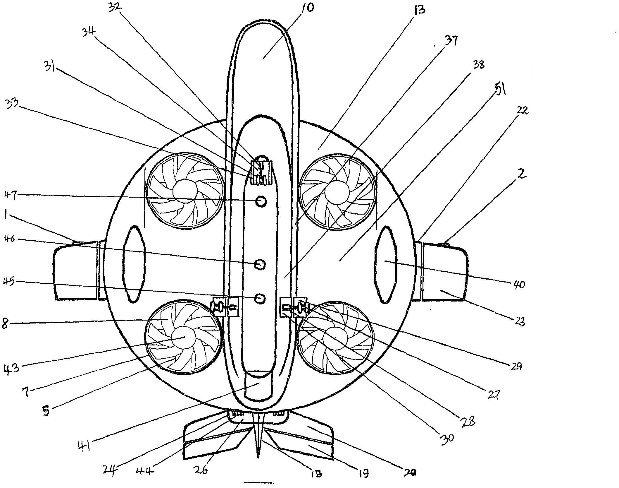
[0031] 1. Identify enterprises with implementation capabilities: 1-Enterprises that use composite materials to design and manufacture various aircraft fuselages. 2-Enterprises that design and manufacture various hulls using composite materials. 3-Enterprises that design and manufacture various large-scale composite material accessories. 4-Enterprises that design and manufacture various aircraft fuselages. 5-Large and medium-sized enterprises with various research and development capabilities. Because the investment in designing and manufacturing aircraft is relatively huge, other small companies that are not related to it will not have the ability to implement it.

[0032] Two, determine design scheme and requirement: in order to reach the purpose of implementing zero risk of the present invention, begin by the design and manufacture of the smallest multifunctional helicopter earlier, then develop toward large multifunctional helicopter design and manufacture direction on th...


PUM


Abstract

The invention discloses a design method for a multifunctional helicopter, relates to integration and design of the special functional advantages of fuselages of a flying wing aircraft, a tilt ducted fan aircraft, a tilt-rotor aircraft, an on-water take-off and landing aircraft, a fixed wing aircraft, an U.S. F-35B vertical take-off and landing aircraft, a rotor helicopter and the like onto a fuselage of the multifunctional helicopter and overcomes the defects of the fuselages of the aircrafts. The invention creatively provides a design theory of a round flying wing and discloses the following fusion design method that four fixed ducts and one round flying wing are fused and designed on the fuselage of the fixed wing aircraft only by utilizing the actual area which is only one fourth of the area of the round flying wing; and beneficial arrangement and installation platforms are provided for various functional mechanisms. Therefore, the design method has the effects that the multifunctional helicopter has various functions; the working efficiency of the multifunctional helicopter is improved; compared with the rotor helicopter, the multifunctional helicopter is used for saving energy and reducing emission by over 50 percent; and a wide novel idea is developed for designing and manufacturing various multifunctional helicopters.

Description

technical field [0001] The present invention belongs to the fuselage design of multifunctional helicopter, the design method in the manufacture field, described relates to how to be able to: flying wing type aircraft, tilting ducted fan type aircraft, tilting rotor type aircraft, water take-off and landing aircraft , fixed-wing aircraft, U.S. F-35B vertical take-off and landing fighter, rotary-wing helicopter, etc., the special flight function advantages on their respective fuselages are concentrated together and designed on a fuselage of a multifunctional helicopter. Carry forward its advantages and overcome its shortcomings. Make it achieve the purpose of one machine with multiple functions, improve work efficiency, save energy and reduce emission by more than 50%. Background technique [0002] Flying-wing layout aircraft: The American B-2 bomber uses a fuselage with a wing-body fusion flying-wing layout. And this technology has been widely concerned and utilized by airc...

Claims


Application Information

Patent Timeline
Patent Type & Authority Applications(China)
IPC IPC(8): B64C27/08B64C27/26
Inventor 周景荣
Owner 周景荣
Why Eureka
Try Eureka