Ozone generating apparatus

An ozone generating device and ozonation technology are applied in ozone preparation, ozone preparation by discharge method, oxygen/ozone/oxide/hydroxide, etc., which can solve the problems of difficulty in maintaining discharge gap and inability to perform uniform discharge, etc.

Inactive Publication Date: 2012-07-04
KK TOSHIBA
View PDF5 Cites 24 Cited by
  • Summary
  • Abstract
  • Description
  • Claims
  • Application Information

AI Technical Summary

Problems solved by technology

However, if the discharge gap length is too short, it will be difficult to

Method used


Image

  • Ozone generating apparatus
  • Ozone generating apparatus
  • Ozone generating apparatus

Examples


Embodiment Construction

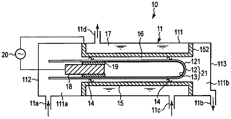
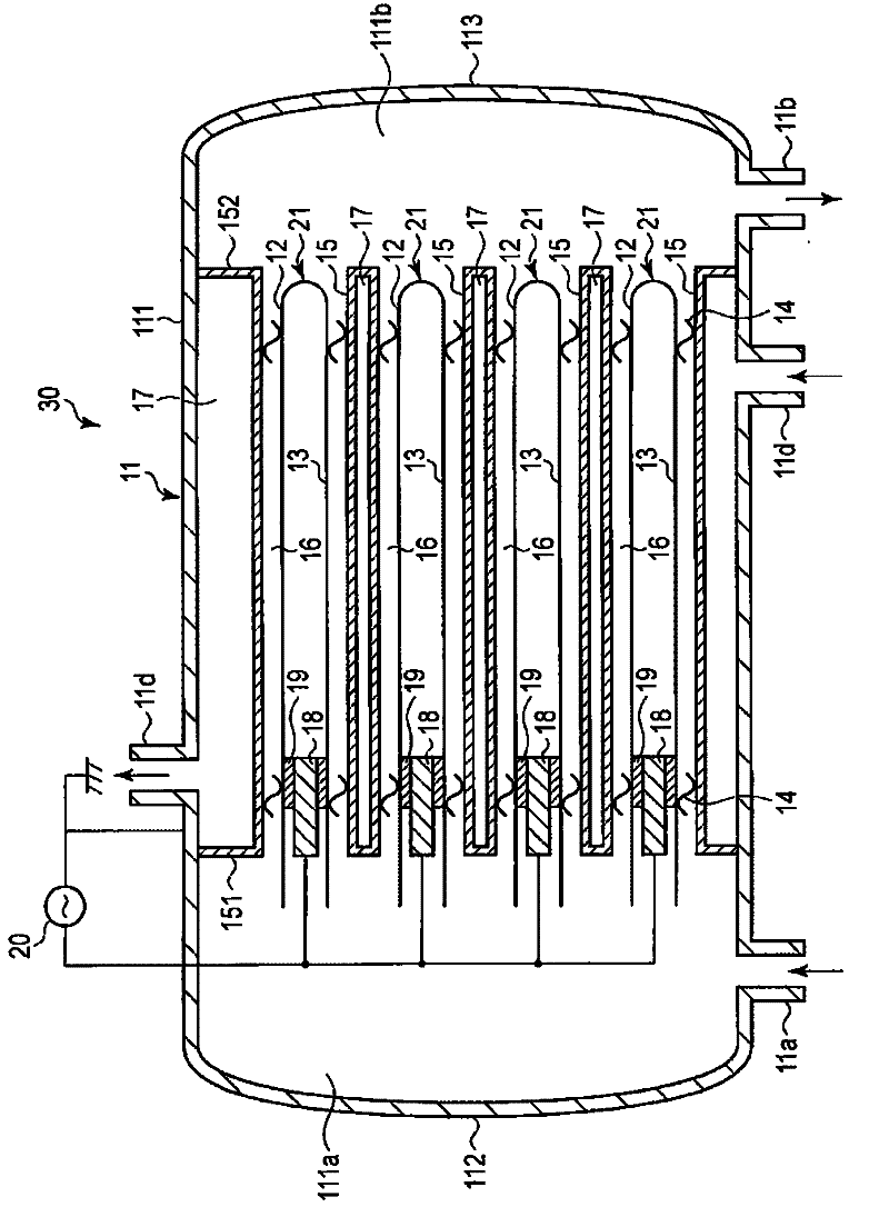
[0017] An ozone generator according to one embodiment generates an ozonated gas from a source gas containing oxygen. The ozone generating device is provided with: a cylindrical airtight container with an inlet of the raw material gas and an outlet of the ozonated gas; a discharge tube including a dielectric tube disposed in the container and a discharge tube disposed inside the dielectric tube. a first electrode; a second electrode, spaced apart from the discharge tube and disposed in the airtight container surrounding the first electrode, so as to form a discharge gap between the second electrode and the discharge tube; a discharge voltage source configured to apply a discharge voltage between the first electrode and the second electrode; and a cooling water jacket surrounding the second electrode. The dielectric tube has an outer diameter of 12 mm or more and 19 mm or less.

[0018] Here, if the outer diameter of the dielectric tube exceeds the range of 12 mm or more and 19...


PUM


Abstract

An ozone generating apparatus according to one embodiment includes a hollow cylindrical sealed container provided with an inlet for a feed gas containing oxygen gas and an outlet for an ozonized gas. A discharge tube including a dielectric tube arranged within the container and a first electrode arranged within the dielectric tube is provided in the container. A second electrode is arranged within the container and surrounds the first electrode, spaced apart from the dielectric tube to form a discharge gap between the second electrode and the dielectric tube. The apparatus further includes a discharge voltage source configured to apply a discharging voltage across the first and second electrodes, and a cooling water jacket surrounding the second electrode. The dielectric tube has an outer diameter of 12 mm or more, but 19 mm or less.

Description

[0001] Cross-reference to related applications: This application is based on Japanese patent application 2010-284495 (filing date: December 21, 2010), and enjoys the priority right of this Japanese application, and by referring to this Japanese application, the entire content of this application is included . technical field [0002] Embodiments of the invention generally relate to ozone generating devices. Background technique [0003] Generally, an ozone generator includes a dielectric tube formed of a dielectric such as glass, and a conductive mold is formed as a first electrode on the inner surface of the dielectric tube. The conductive mold forms a dielectric electrode together with the dielectric tube. A cylindrical second electrode is provided outside the dielectric tube so as to surround the first electrode. A spacer is interposed between the dielectric tube and the second electrode, forming a tiny discharge gap. A source gas containing oxygen flows in the discharg...

Claims


Application Information

Patent Timeline
IPC IPC(8): C01B13/11
CPCC01B2201/14C01B2201/32C01B13/11C01B2201/22C01B2201/76C01B2201/64
Inventor 村田隆昭雨森清行牧濑龙太郎中岛可南子纳田和彦桥本美智子
Owner KK TOSHIBA
Why Eureka
Try Eureka