Sheet material cutting method and automatic cutting machine

A cutting machine and sheet material technology, which is applied in the cutting of textile materials, textiles and papermaking, etc., can solve problems such as the decrease in the value of clothing materials

Active Publication Date: 2012-07-04
SHIMA SEIKI MFG LTD
View PDF7 Cites 28 Cited by
  • Summary
  • Abstract
  • Description
  • Claims
  • Application Information

AI Technical Summary

Problems solved by technology

If the characteristic pattern of each part such as the front body and sleeves...

Method used


Image

  • Sheet material cutting method and automatic cutting machine
  • Sheet material cutting method and automatic cutting machine
  • Sheet material cutting method and automatic cutting machine

Examples


Embodiment approach 1

[0084]

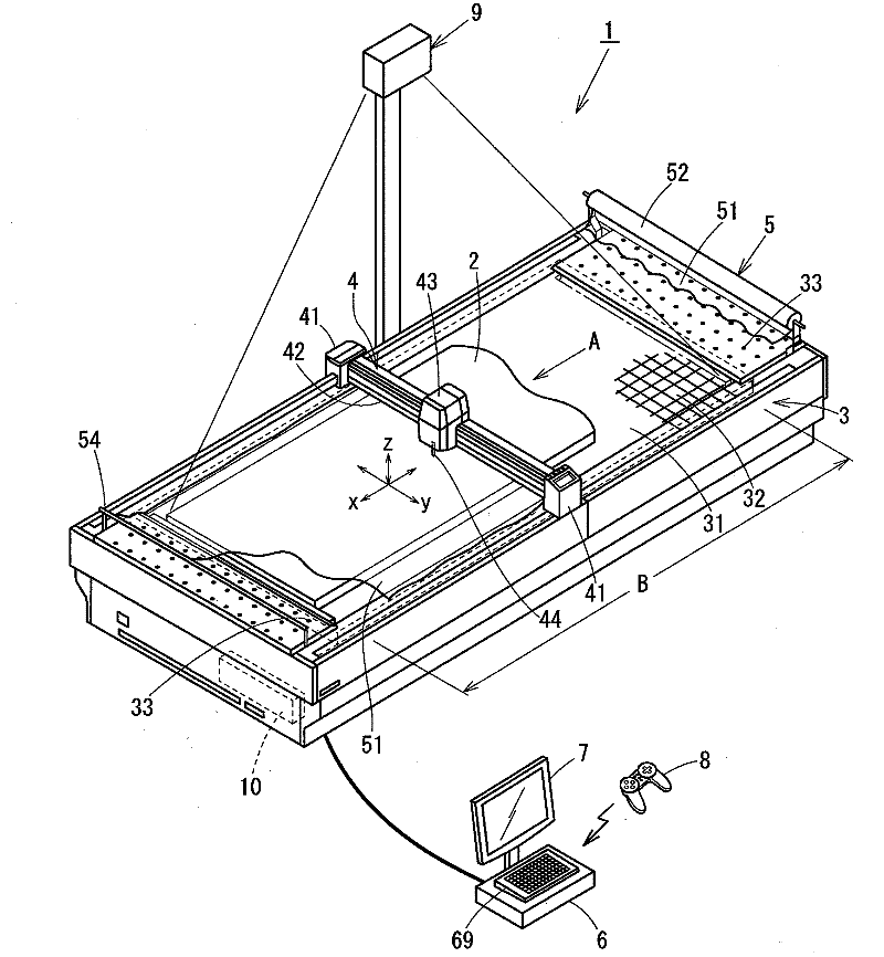
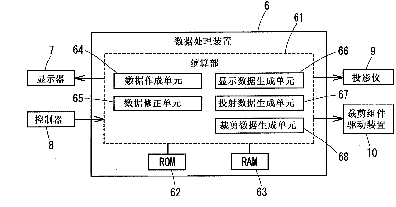
[0085] figure 1 The whole structure of the automatic cutting machine which implements the cutting method of this invention is shown. The automatic cutting machine 1 is composed of a cutting machine body 3 , a cutting assembly 4 , a cover sheet feeding device 5 , a data processing device 6 , a display 7 , a controller 8 , a projector 9 and a cutting assembly driving device 10 .

[0086] A workbench 31 is provided on the upper surface of the cutter body 3, and the workbench 31 is loaded with a patterned sheet 2 to be cut (partially cut out and shown in the figure). The table 31 is constituted by a conveyor belt, and the sheet 2 fed out from a laying device (not shown) is conveyed in the direction of arrow A by the conveyor belt and spreads on the table 31 . The surface of the table 31 is covered with a bristle brush 32 (only partially shown) to prevent the table 31 from being cut during cutting.

[0087] In the following description, such as figure 1 As shown, the ...

Embodiment approach 2

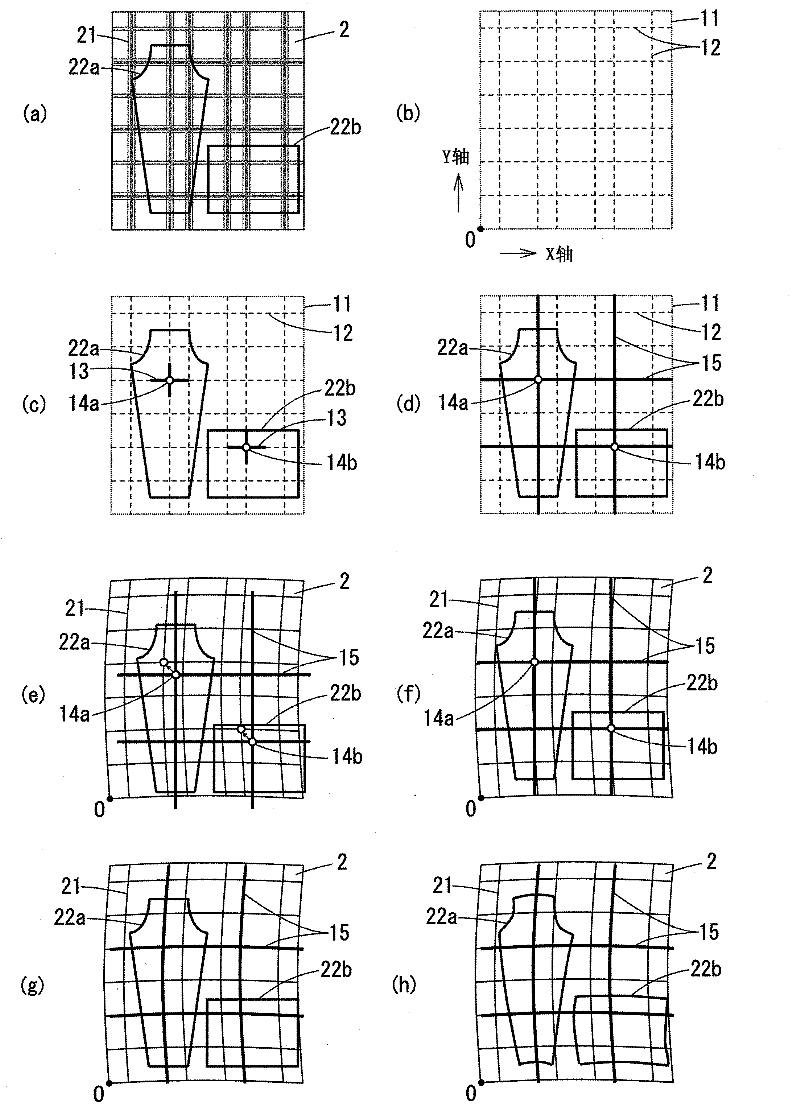
[0144] In Embodiment 1, the cutting of the sheet having the checkered pattern was described, but the processing steps up to cutting are slightly different in the cutting of the sheet having the striped pattern. In this embodiment, refer to Figure 5 , the processing procedure in the case of cutting a sheet having a striped pattern will be described focusing on points different from cutting a sheet having a checkered pattern.

[0145] Figure 5 In (a), the patterns of the parts 22a and 22b to be cut are arranged on the sheet material 2A having the pattern 21A of stripe-like vertical stripes. and figure 2 Similarly, for easy understanding of the description, a state in which two parts are arranged on the square sheet 2A is shown.

[0146] Unlike a checkered pattern, when cutting a sheet with a striped pattern, there is little need to consider pattern matching in a direction parallel to the stripes, so the content of processing when cutting the sheet is different accordingly....

Embodiment approach 3

[0155] When cutting a plurality of parts with different patterns arranged on a sheet, since the reference patterns are scattered and arranged on the sheet, data required for correction of coordinate data are scattered on a virtual plane. On the other hand, when offset occurs in the arrangement of the reference pattern as in the case where the parts of the elongated pattern are offset on the sheet, data required for correction of the coordinate data is insufficient depending on the position.

[0156] When the data of the part pattern is corrected based on such data, the error from the actual deformation increases, and the reliability of the cutting data decreases. In this embodiment, a method of supplementing data when an offset occurs in the arrangement of the reference pattern will be described.

[0157] Image 6 It shows a state in which the theoretical pattern pattern 12B, the patterns 22c to 22f of the respective parts, and the reference pattern are arranged on the virtua...


PUM


Abstract

The present invention provides a sheet material cutting method and an automatic cutting machine. The method is used for cutting the sheet which is carried on a worktable and is provided with patterns along the pattern of garment piece, wherein the data for cutting are corrected according to the garment piece deformation. A garment piece pattern (22) is configured on a theoretical pattern (12) of the sheet material which is formed on an imaginary plane (11) that corresponds with the sheet material (2), and pattern matching points (14) are set according to each garment piece. Afterwards, a reference pattern (15) which comprises the pattern matching points (14) are formed on the imaginary plane (11). Afterwards, a projector is used for projecting the matching points (14) and the reference pattern (15) with an actual dimension. Furthermore the shape of the reference pattern (15) deforms for matching with the shape of the pattern of the sheet material (2), thereby correcting coordinate data of the reference pattern (15). The coordinate data of the pattern (22) of the garment piece are corrected corresponding to the corrected reference pattern (15), and the sheet material is cut based on the coordinate data.

Description

technical field [0001] The present invention relates to a method of cutting a sheet of cloth or the like placed on a table into garment parts of a predetermined pattern, and an automatic cutting machine using the method. Background technique [0002] When processing cloth or fabric into products such as clothing, it is necessary to cut each part such as a front body, a back body, and sleeves from a sheet material such as cloth. Usually, an automatic cutting machine is used to cut the sheet placed on the table based on the shape data of each part output from the controller. [0003] On the other hand, when fabrics or the like are produced using a patterned sheet, it is necessary to match the pattern in the process of sewing each part. If the pattern characteristic of each part, such as a front body and sleeves, does not match after sewing, the commodity value as clothing material will fall. [0004] However, pattern matching work is difficult only in the sewing process, and...

Claims


Application Information

Patent Timeline
IPC IPC(8): D06H7/00
Inventor 滨一成
Owner SHIMA SEIKI MFG LTD
Why Eureka
Try Eureka