Piston for an internal combustion engine

A technology for internal combustion engines and pistons, which is applied in the field of pistons for internal combustion engines, and can solve problems such as optimizing cooling media

Inactive Publication Date: 2012-07-04
MAHLE INT GMBH
View PDF7 Cites 7 Cited by
  • Summary
  • Abstract
  • Description
  • Claims
  • Application Information

AI Technical Summary

Problems solved by technology

The problem is that it is necessary to optimize the cooling efficiency of the cooling medium circulating in the cooling channel

Method used


Image

  • Piston for an internal combustion engine
  • Piston for an internal combustion engine
  • Piston for an internal combustion engine

Examples


Embodiment Construction

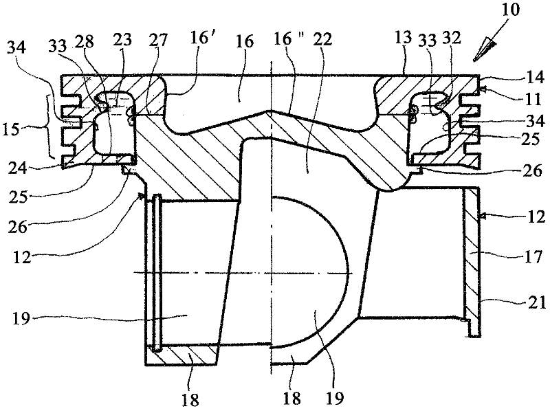
[0021] figure 1 A first embodiment of a piston 10 according to the invention is shown. The piston 10 is composed of a first piston member 11 and a second piston member 12 . In the present embodiment, the first piston component 11 is provided as a piston ring part, and the second piston component 12 is provided as a piston base body for a box piston. Other divisions are also conceivable, the annular band 15 (see below) being formed at least in the region of the free end 24 (see below) of the first piston component 11 . Both members can be made from any suitable metallic material.

[0022] In the exemplary embodiment, the first piston component 11 has a piston crown 13 as well as an annular land 14 and an annular band 15 having annular grooves for receiving piston rings (not shown). The first piston component 11 also forms a wall region 16 ′ of the combustion chamber cavity 16 .

[0023] In the present exemplary embodiment, the second piston component 12 forms a piston skirt...


PUM


Abstract

The present invention relates to a piston (10, 110, 210, 310) for an internal combustion engine, having a first piston component (11) and a second piston component (12), which jointly form a circumferential cooling channel (23) that is open toward the second piston component (12), whereby the first piston component (11) forms at least a part of a piston crown (13) as well as an outer circumferential wall (34) of the cooling channel, characterized in that the outer circumferential wall (34) of the cooling channel (23) has a circumferential projection (32) below the piston crown (13), which projection is provided with a circumferential guide surface (33) for coolant, directed radially inward.

Description

technical field [0001] The invention relates to a piston for an internal combustion engine, comprising a first piston component and a second piston component, the two piston components together forming an annular cooling channel opening towards the second piston component, the cooling channel passing through Ring seals for sealing. Background technique [0002] Such pistons with annular cooling channels are known. The problem with this is that it is necessary to optimize the cooling efficiency of the cooling medium circulating in the cooling channel. To this end, it is necessary that the cooling medium be conveyed as specifically as possible to specific regions of the piston which are exposed to high temperatures during engine operation. This concerns in particular the region of the cooling channel which is located below the piston crown, since the piston crown is exposed to the full combustion temperature during operation and thus has to dissipate a considerable amount of...

Claims


Application Information

Patent Timeline
Patent Type & Authority Applications(China)
IPC IPC(8): F02F3/22F02F11/00
CPCF02F3/003F02F3/22
Inventor 赖纳·沙普米夏埃尔·乌尔里希
Owner MAHLE INT GMBH
Why Eureka
Try Eureka