Clutch device

A clutch device, clutch technology, applied in clutches, friction clutches, fluid-driven clutches, etc., can solve problems such as difficult assembly or installation, and achieve the effect of simplified installation and simplified operation

Active Publication Date: 2012-07-04
BORGWARNER INC
View PDF5 Cites 26 Cited by
  • Summary
  • Abstract
  • Description
  • Claims
  • Application Information

AI Technical Summary

Problems solved by technology

Known clutch arrangements have proven successful, but as they are difficult to assemble or install, improvements are also needed

Method used


Image

  • Clutch device
  • Clutch device
  • Clutch device

Examples


Embodiment Construction

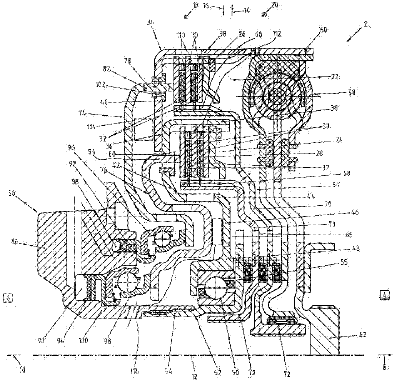
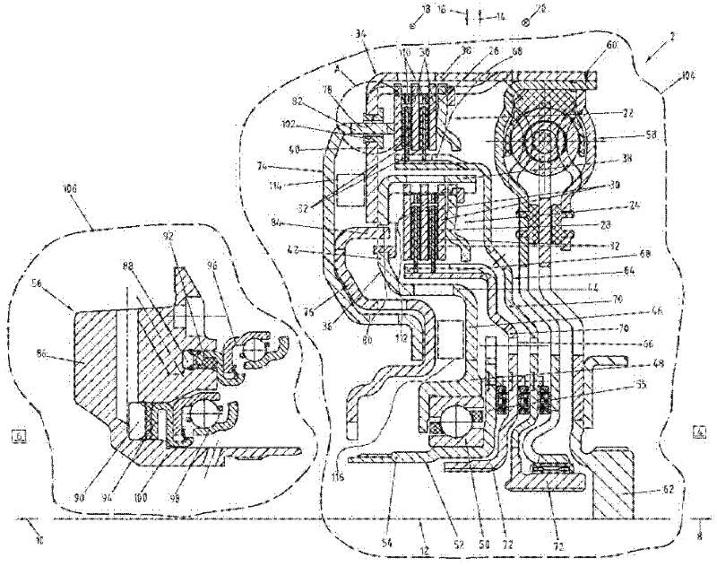
[0044] figure 1 with figure 2 An embodiment of a clutch device 2 according to the invention is shown. The clutch device 2 is designed as a multi-plate clutch device, which in the present case is a double clutch device. Rather, it's a concentric dual-clutch setup. The clutch device 2 is arranged between a drive unit 4 and a transmission 6 in the drive train of the motor vehicle, the drive unit being figure 1 is only schematically shown in the drawings, the transmission is likewise only schematically shown in these figures. The drive unit 4 is preferably formed by an internal combustion engine, particularly preferably a piston engine or reciprocating engine, while the transmission 6 is a dual clutch transmission. The clutch device 2 is arranged in mutually opposite axial directions 8 , 10 between the drive unit 4 and the transmission 6 , the rotational axis 12 of the clutch device 2 extends in mutually opposite axial directions 8 , 10 . Furthermore, in these figures, the o...


PUM


Abstract

A clutch device for arrangement in a drive train of a motor vehicle between a drive unit and a transmission is provided. The clutch device may include a multiple-disk clutch arrangement for selective torque transfer between the drive unit and the transmission. The multiple-disk clutch arrangement may be actuable via a force transfer element supported on a disk carrier of the multiple-disk clutch arrangement.

Description

technical field [0001] The invention relates to a clutch device arranged between a drive unit and a transmission in the drive train of a motor vehicle, the clutch device having associated with a transmission input shaft for connecting between the drive unit and the transmission input shaft At least one multi-plate clutch arrangement selectively transmitting torque is actuatable by a force transmitting element. Background technique [0002] Clutch arrangements arranged between a drive unit and a transmission are known from the prior art and have at least one multi-plate clutch arrangement which is actuatable via a force transmission element. Known clutch arrangements have proven successful, but as they are difficult to assemble or install there is a need for improvement as well. Contents of the invention [0003] It is therefore an object of the present invention to provide a clutch arrangement, preferably a multiple clutch arrangement, which is particularly simple to asse...

Claims


Application Information

Patent Timeline
Patent Type & Authority Applications(China)
IPC IPC(8): F16D25/10F16D25/12
CPCF16D2021/0661F16D21/06F16D13/70F16D25/082F16D2300/12F16D25/10F16D2013/581
Inventor H·J·哈伍克T·扎科
Owner BORGWARNER INC
Why Eureka
Try Eureka