Eureka AIR delivers breakthrough ideas for toughest innovation challenges, trusted by R&D personnel around the world.

Rocker-type continuously variable transmission

A continuously variable transmission and rocker type technology, applied in the direction of belt/chain/gear, mechanical equipment, transmission device, etc., can solve the problems of engine and transmission system impact, discontinuous speed change process, discontinuous speed change, etc., to achieve power transmission Smooth, reliable power transmission, eliminating the effect of instantaneous impact

Inactive Publication Date: 2012-07-04
DALIAN MARITIME UNIVERSITY
View PDF5 Cites 15 Cited by
  • Summary
  • Abstract
  • Description
  • Claims
  • Application Information

AI Technical Summary

Problems solved by technology

Purely mechanical transmissions are commonly used at present, including manual, automatic, manual transmission, and continuously variable transmission. Manual transmissions are cumbersome to operate and cannot continuously change gears; although automatic and manual transmissions can solve the trouble of frequent gear changes, the operation is easy. However, the impact on the engine and transmission system during automatic shifting is inevitable, and the transmission ratio can only be selected among several fixed values, and the transmission process is discontinuous; in this case, although the CVT continuously variable transmission technology overcomes the However, CVT technology has to rely on friction transmission, which inevitably limits the application of CVT.

Method used


Image

  • Rocker-type continuously variable transmission
  • Rocker-type continuously variable transmission
  • Rocker-type continuously variable transmission

Examples


Embodiment Construction

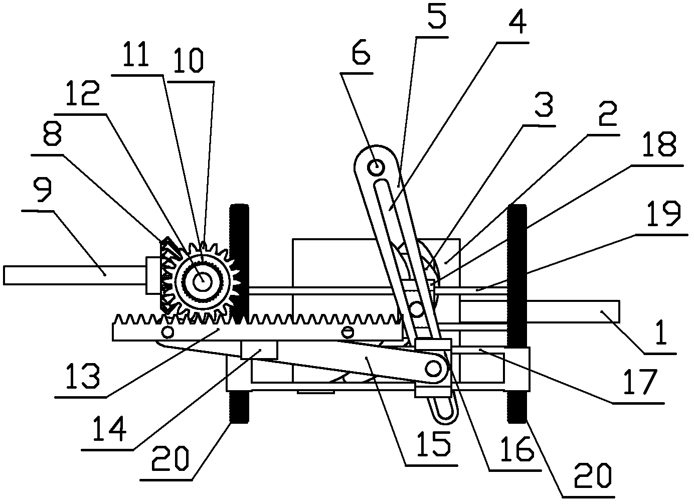
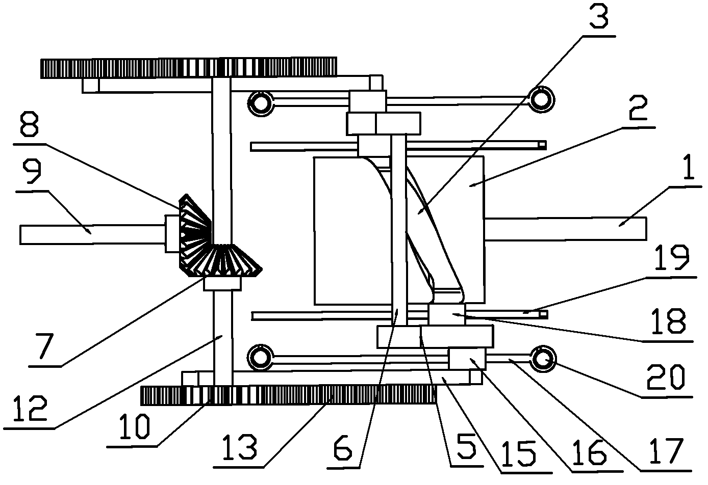
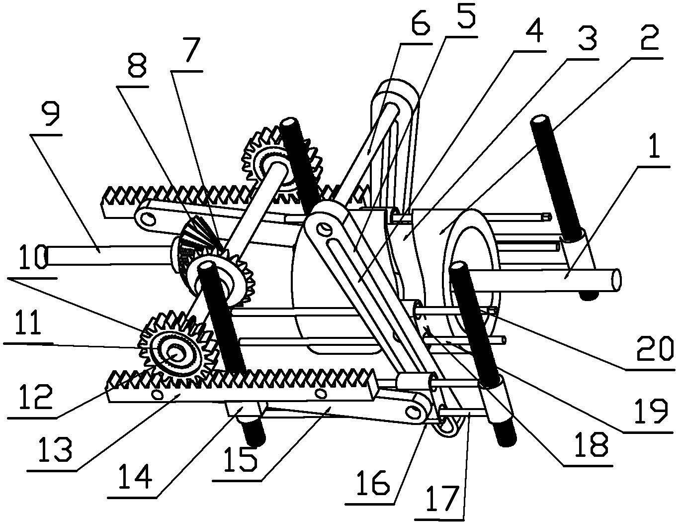
[0039] The specific embodiment of the present invention is shown in the attached drawings, and its structure is that a slider I18, a slide I19, a rocker 5, a slider II and a slider I18 are installed on the slide I19 symmetrically on both sides of the cylindrical cam 2. The roller on one side of the slider Ⅰ18 is installed in the slideway 3 of the cylindrical cam 2, and the roller on the other side is embedded in the slide groove 4 of the rocker 5; the slider Ⅱ16 is installed on the slideway Ⅱ17, and the slider Ⅱ16 is one The roller on one side is embedded in the sliding groove 4 of the rocker 5, and the other side is flexibly connected to the bottom of the connecting rod 15; the connecting rod 15 is connected with the rack 13 through the rack bracket 14, and the rack 13 meshes with the spur gear 10 The spur gear 10 is equipped with a one-way bearing 11; a gear shaft 12 is installed between the two one-way bearings 11, a bevel gear I7 is installed in the middle of the gear shaft ...


PUM


Abstract

The invention discloses a rocker-type continuously variable transmission, which relates to a mechanical continuously variable transmission for a vehicle. The rocker-type continuously variable transmission is structurally characterized in that sliders I, slide ways I, rockers, sliders II, slide ways II, connecting rods, racks, straight gears and one-way bearings are symmetrically and sequentially mounted on two sides of a cylindrical cam, the sliders I are mounted on the corresponding slide ways I, a roller on one side of each slider I is mounted in a slide way of the cylindrical cam, a roller on the other side of each slider I is embedded into a slide groove of one rocker, the sliders II are mounted on the corresponding slide ways II, a roller on one side of each slider II is embedded into a slide groove of the other rocker, the other side of each slider II is movably connected with the bottom of each connecting rod, the connecting rods are connected with the corresponding racks through rack supporting grooves, the racks are engaged with the straight gears, the one-way bearings are mounted in the straight gears, a gear shaft is mounted between the two one-way bearings, a bevel gear I is mounted in the middle of the gear shaft and engaged with a bevel gear II, a power output shaft is mounted on the bevel gear II, the front ends of the two opposite rockers are connected with each other by a rocker shaft, and a power input shaft is mounted at the bottom of the cylindrical cam.

Description

Technical field [0001] The rocker type continuously variable transmission according to the present invention relates to a mechanical continuously variable transmission for vehicles. Background technique [0002] Gearboxes are widely used in daily life and production, especially in the automotive industry. Purely mechanical gearboxes are currently commonly used in manual, automatic, manual-automatic, and continuously variable transmissions. Manual transmissions are cumbersome to operate and cannot be continuously shifted. Although automatic and manual transmissions can solve the trouble of frequent shifting, the operation is easy and free. However, the impact on the engine and transmission system during automatic shifting is inevitable, and the transmission ratio can only be selected among several fixed values, and the transmission process is not continuous; in this case, the CVT continuously variable transmission technology can overcome To overcome the shortcomings of discontinu...

Claims


Application Information

Patent Timeline
Patent Type & Authority Applications(China)
IPC IPC(8): F16H37/12
Inventor 李冰梅秦宇
Owner DALIAN MARITIME UNIVERSITY
Why Eureka
Eureka Blog
Learn More