Pressure regulating valve, particularly for controlling a clutch in a motor vehicle automatic transmission

A technology of automatic transmission and pressure regulating valve, applied in the field of pressure regulating valve, can solve the problems of short reversing time and large flow, and achieve the effect of reducing axial force component and durable reversing performance

Active Publication Date: 2012-07-04
ROBERT BOSCH GMBH
View PDF7 Cites 2 Cited by
  • Summary
  • Abstract
  • Description
  • Claims
  • Application Information

AI Technical Summary

Problems solved by technology

However, this has an adverse effect on the relatively high flow rates and short reversing times required by modern automatic transmissions

Method used


Image

  • Pressure regulating valve, particularly for controlling a clutch in a motor vehicle automatic transmission
  • Pressure regulating valve, particularly for controlling a clutch in a motor vehicle automatic transmission
  • Pressure regulating valve, particularly for controlling a clutch in a motor vehicle automatic transmission

Examples


Embodiment Construction

[0019] The functionally equivalent elements and dimensions in all the drawings also use the same reference symbols in different embodiments.

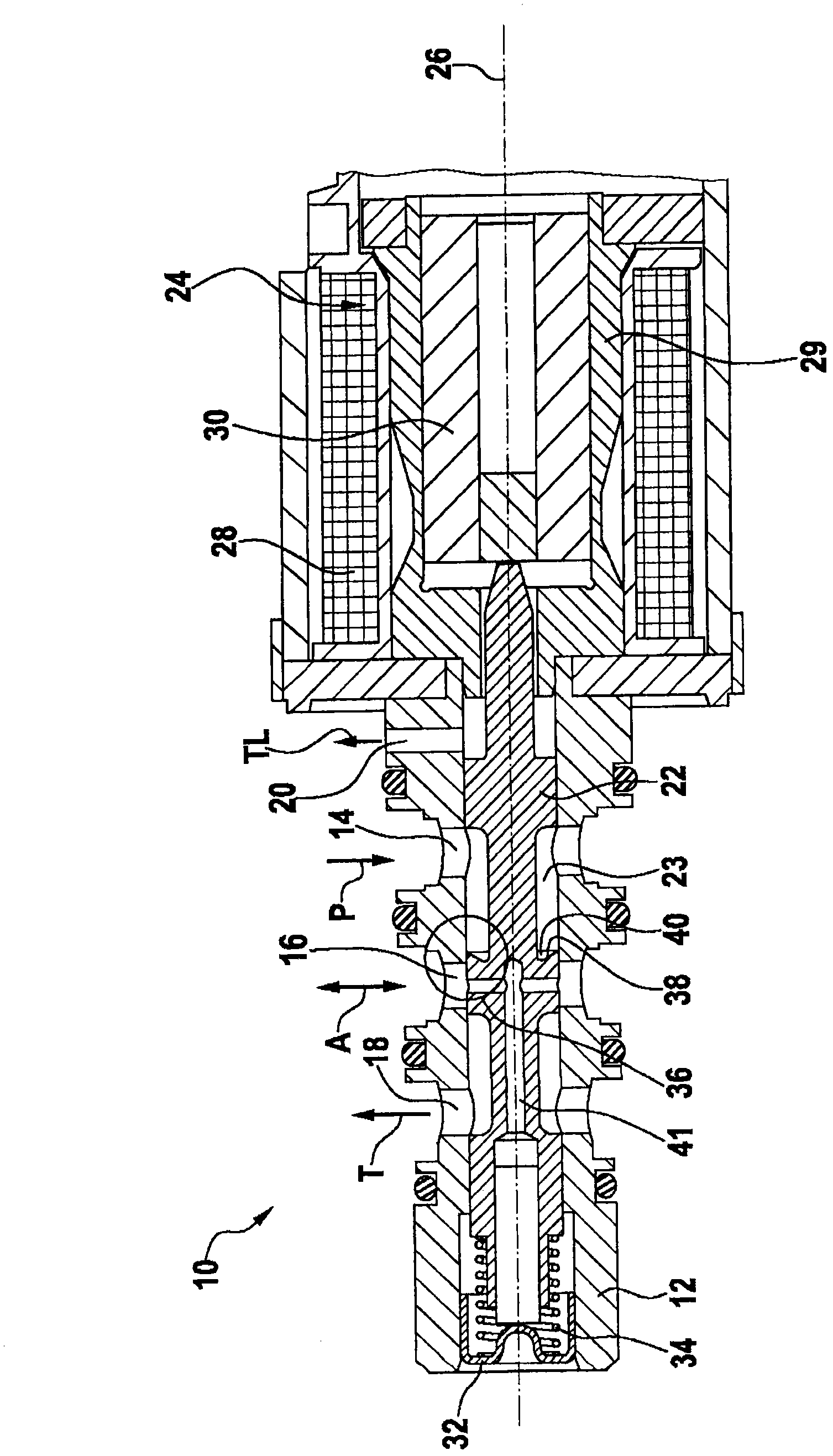
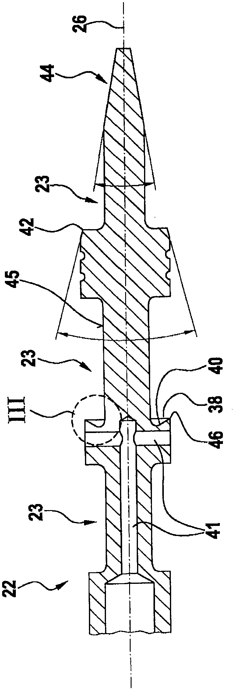
[0020] figure 1 A pressure regulating valve 10 for controlling a clutch in an automatic transmission of an automobile is shown in an axial sectional view. The pressure regulating valve includes a cylindrical housing 12 with a first transverse opening as a transverse hole 14 and a second transverse opening as a transverse hole 16, viewed in the direction of the longitudinal axis 26, spaced apart from each other (axial Distance), and has other horizontal holes 18 and 20. A valve core 22 coaxial with the housing 12 is provided in the housing 12. The valve core 22 can be moved axially by the electromagnet 24 in the direction of the longitudinal axis 26. The piston-like spool 22 now includes three grooves 23 extending in the direction of the longitudinal axis 26 ("axial extension"), which respectively extend in the form of annular grooves ove...


PUM


Abstract

A pressure regulating valve (10) for controlling a clutch in a motor vehicle automatic transmission, having a housing (12) having a first transverse opening (14) which acts as a fluid inlet, and a second transverse opening (16) which acts at least temporarily as a fluid outlet, the two transverse openings (14, 16) being spaced axially from one another, and having a valve slide (22) guided in the housing (12), the valve slide including an axially extending recess (23) in its circumferential surface, the recess fluidically connecting the two transverse openings (14, 16) to one another in a first axial position of the valve slide (22) and separating them from one another in a second axial position, in the circumferential surface of the valve slide (22) the recess (23) having a face (38) having an undercut (40) at its end closest to the second transverse opening (16).

Description

Technical field [0001] The invention relates to a pressure regulating valve according to the preamble of claim 1. Background technique [0002] A voltage regulator for controlling a clutch in an automatic transmission of an automobile is well known in the market. Such a pressure regulator is operated by means of an electromagnet, which can send the axially movable piston of the slide valve into at least two end positions or reversing positions. When the electromagnet is switched on, the piston is displaced axially, so that the control edge of the piston can release the opening of the slide valve, so that, for example, a fluid flow can flow into the adjustment part of the clutch. [0003] The liquid flow flowing through the opening additionally generates an axial force component. The greater the force component, the greater the deviation of the direction of the liquid flow from the required radial direction. The axial force component opposes the force of the electromagnet and redu...

Claims


Application Information

Patent Timeline
Patent Type & Authority Applications(China)
IPC IPC(8): F16K11/07F16K3/30F16H61/02
CPCF16H61/0251F16K11/0708F16K31/0613F16H61/06F16H61/00
Inventor W·施密德
Owner ROBERT BOSCH GMBH
Why Eureka
Try Eureka