Oil tank water discharge liquid storage self force driving oil blocking device

A driving device and liquid storage technology, applied in the direction of valve operation/release devices, valve devices, engine components, etc., can solve the problems of increasing the amount of oil in the drainage process, complex structure, and impact

Inactive Publication Date: 2012-07-04
LOGISTICAL ENGINEERING UNIVERSITY OF PLA
View PDF5 Cites 6 Cited by
  • Summary
  • Abstract
  • Description
  • Claims
  • Application Information

AI Technical Summary

Problems solved by technology

There is also a device that detects the position of the oil-water interface based on the probe, and controls the drainage process by an electric valve, but the device must have a power supply, and the structure is complex, with many influencing factors, and reliability is not easy to guarantee, especially the use of electric valves has problems affecting the safety of oil depots.
There is also a single-float water cut-off valve that uses the difference in specific gravity of the liquid flow to control the drainage process. This single-float water cut-off valve must first let go of the oil storage head before discharging water, and it is necessary to manually lift the float to open the valve core to drain the water. pressure, which not only increases the amount of oil carried in the drainage process, but also is greatly affected by human factors, which reduces the reliability of the operation

Method used


Image

  • Oil tank water discharge liquid storage self force driving oil blocking device
  • Oil tank water discharge liquid storage self force driving oil blocking device
  • Oil tank water discharge liquid storage self force driving oil blocking device

Examples


Embodiment Construction

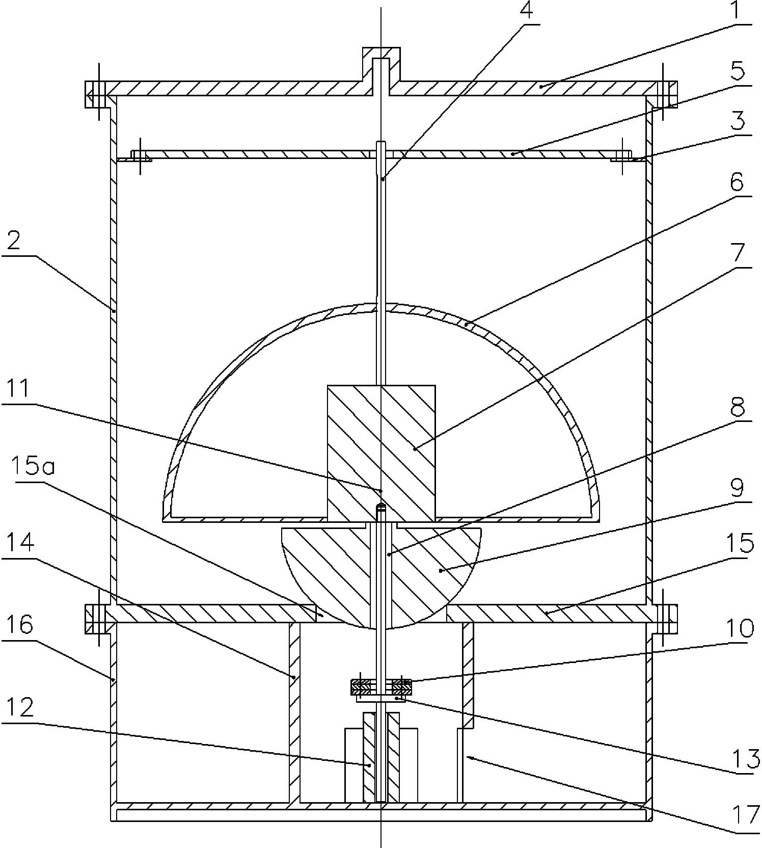
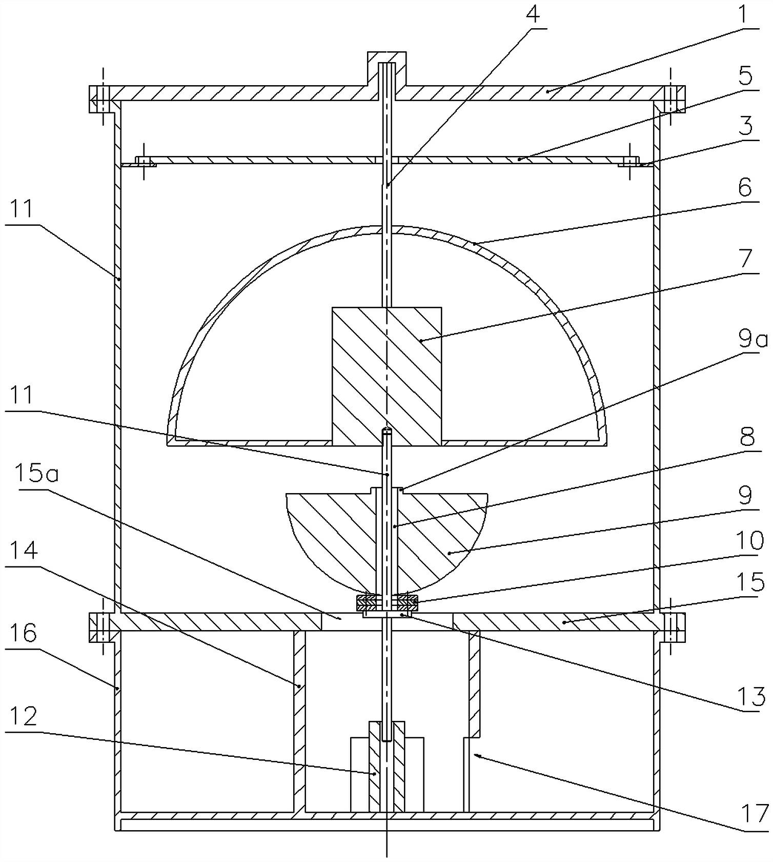
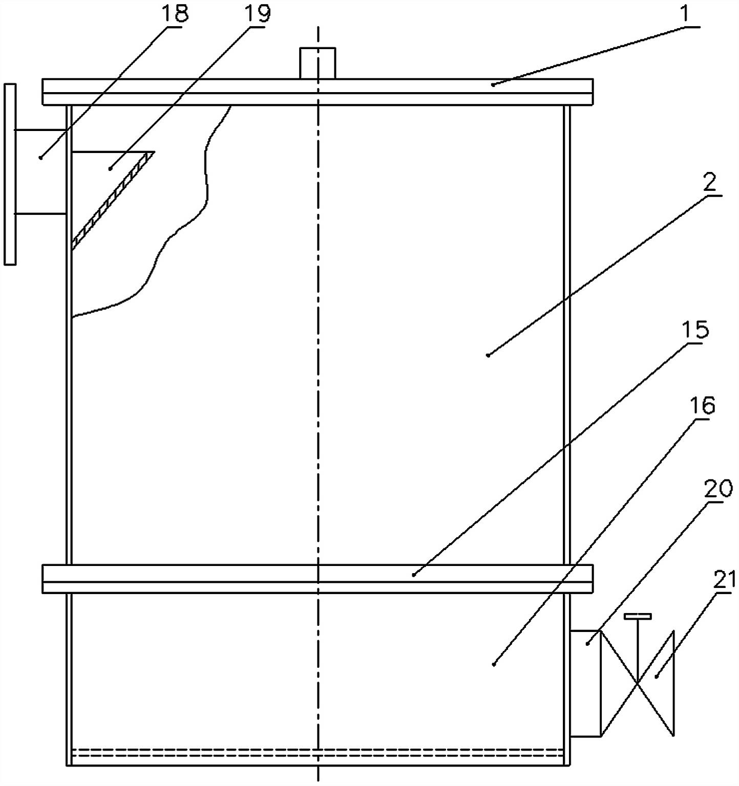
[0025] see figure 1 , figure 2, a liquid storage self-driven oil-repelling device for oil tank drainage, including a drain tank 16, a drain pipe 20 at the outlet of the drain tank 16 is equipped with a drain valve 21, and the bottom water entering the drain tank 16 can be discharged by opening the drain valve 21. The upper end of described drain tank 16 is provided with a liquid separation tank 2, and the upper end of liquid separation tank 2 is provided with case lid 1, and case lid 1 is fixedly connected with casing by bolt, and establishes sealing gasket sealing, opens case lid 1 and can divide liquid The inside of the box 2 is cleaned and maintained. The liquid inlet pipe 18 is provided on the upper part of the side wall of the liquid separation box 2, which is used to connect with the bottom pipe of the oil tank. The liquid inlet pipe 18 is fixed on the liquid separation box 2 by welding, or fixed on the liquid separation box 2 by flange connection . In order to avoid...


PUM


Abstract

The invention relates to an oil tank water discharge liquid storage self force driving oil blocking device. A water discharge valve is arranged on a water discharge groove, the upper end of the water discharge groove is provided with a liquid dividing tank, the liquid dividing tank and the water discharge groove are separated into two spaces by a separation plate, are communicated through a waterpassing hole arranged on the separation plate and form the fall head, a buoyancy control valve body is arranged at the water passing hole, a pressure relief hole is arranged on the valve body, a floating body with the specific gravity greater than that of the oil but smaller than that of water is arranged in the liquid dividing box for pressing the pressure relief hole for forming a closed state,an upper guide rod is arranged on the floating body and is in gap matching with a guide hole arranged on a positioning frame, the lower end of the floating body is connected with a lower guide rod, the lower guide rod penetrates through the pressure relief hole, in addition, a flow passing gap is formed, the lower part of the lower guide rod is in gap matching with a guide hole of a guide seat, avalve body opening driving device is arranged on the lower guide rod, and the liquid dividing box is provided with a liquid inlet pipe. The oil and water specific gravity differences are utilized forforming different buoyancies to control the sinking and floating of the floating body, the opening for discharging the bottom water in the oil tank can be realized, the automatic closing during oil liquid contact can also be realized, and oil liquid is prevented from flowing out in large quantities during the bottom water discharge.

Description

technical field [0001] The invention relates to an oil tank bottom water discharge device of an oil storage tank, in particular to a liquid storage self-driven oil blocking device for oil tank drainage. Background technique [0002] At present, the oil tank bottom water discharge device of the oil storage tank in the oil depot is usually installed at the bottom of the oil tank with a sewage collection tank, a water discharge pipe and a common valve to discharge the water at the bottom of the oil tank; Water pipes and ordinary valves are installed, but siphon water discharge devices are used for discharge. These two bottom water discharge devices rely on the operator to control the start and end of the bottom water discharge process by operating the ordinary valve based on experience, so that the end of each bottom water discharge is oily, and there is a possibility of misoperation and oil leakage , causing oil loss, and will pollute the environment, and even endanger safety...

Claims


Application Information

Patent Timeline
Patent Type & Authority Applications(China)
IPC IPC(8): F16K31/18
Inventor 刘丽川张世峡秦泽农束秀梅黄磊秦玉芳黄锦文
Owner LOGISTICAL ENGINEERING UNIVERSITY OF PLA
Why Eureka
Try Eureka