Gradient sandwiched anti-explosion pot

An explosion-proof tank, gradient type technology, applied in blasting and other directions, can solve the problems of heavy structure, heavy structure of explosion-proof tank, lack of flexibility and mobility, etc., to achieve good anti-explosion performance and reduce impact damage.

Inactive Publication Date: 2012-07-04
XI AN JIAOTONG UNIV
View PDF6 Cites 11 Cited by
  • Summary
  • Abstract
  • Description
  • Claims
  • Application Information

AI Technical Summary

Problems solved by technology

[0002] The existing metal explosion-proof tank has the problem of bulky structure and lack of flexibility, which limits its application range. The Chinese utility model patent ZL200920033823.9 discloses a weak explosion-proof tank with a foam metal sandwich. The inner and outer panels of the tank body fill the space with metal foam to solve the problem of bulky structure of existing explosion-proof tanks, and use the excellent energy-absorbing performance of metal foam to enhance the anti-explosion performance of explosion-proof tanks. However, the explosion-proof tank disclosed in this patent uses a single layer of foam metal as a The core layer does not make full use of the variable density of foam metal to improve the anti-explosion performance of explosion-proof tanks, that is, using foam metal with a gradient density as the sandwich layer can obtain explosion-proof tanks with better anti-explosion performance; at the same time, the patent involves The explosion-proof tank has no top cover, and the metal fragments produced by the explosion will damage the surrounding equipment and people

Method used


Image

  • Gradient sandwiched anti-explosion pot
  • Gradient sandwiched anti-explosion pot
  • Gradient sandwiched anti-explosion pot

Examples


Embodiment Construction

[0021] The structural principle and working principle of the present invention will be described in more detail below in conjunction with the accompanying drawings.

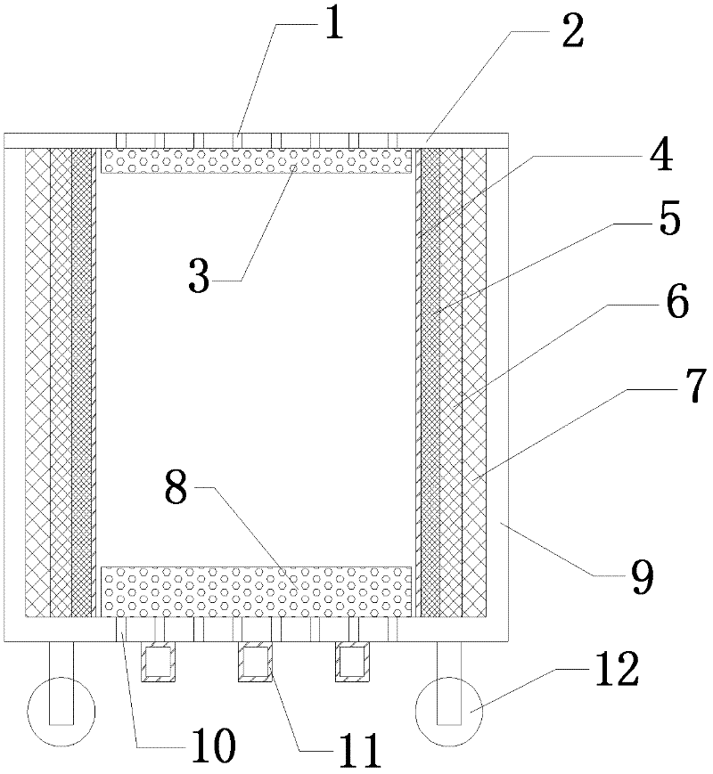
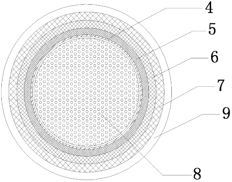
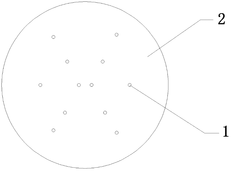
[0022] like figure 1 As shown, a gradient type sandwich explosion-proof tank of the present invention includes a cover plate pressure relief hole 1, a cover plate 2, a buffer lining plate 3, an inner cylinder 4, an inner buffer layer 5, a middle buffer layer 6, an outer buffer layer 7, Buffer plate 8, outer cylinder 9, outer cylinder pressure relief hole 10, reinforcing rib 11 and caster 12, cover plate 2 and buffer lining plate 3 form the top cover and cover plate pressure relief hole 1 is opened on the cover plate 2, and the inner The cylinder 4, the inner buffer layer 5, the middle buffer layer 6, the outer buffer layer 7 and the outer cylinder 9 form a tank body and have an outer cylinder pressure relief hole 10 on the bottom plate of the outer cylinder 9, and the inner buffer layer 5, the middle buffer layer...


PUM


Abstract

The invention discloses a gradient sandwiched anti-explosion pot, comprising a pot body and a pot bottom, wherein the pot body is composed of an inner barrel, an inner buffer layer, a middle buffer layer, an outer buffer layer and an outer barrel; the inner buffer layer, the middle buffer layer and the outer buffer layer are made of closed cell foam metals and the density of the closed cell foam metal from the inner buffer layer, the middle buffer layer to the outer buffer layer is reduced gradually; a cover plate with a pressure relief hole is formed at the top of the pot body; the pot bottom is a bottom plate of the outer barrel; buffer base plates are installed on the upper part of the bottom plate of the outer barrel and the inner part of the inner barrel; a pressure relief hole is formed on the bottom plate of the outer barrel; buffer lining plates are installed at the lower part of the cover plate and the inner part of the inner barrel; the buffer lining plate and the buffer base plates are made of opening-hole foam metals; the thickness of the buffer base plate is more than that of the buffer lining plate; the thickness of the outer barrel is more than that of the inner barrel; the multilayer foam metal of which the density is reduced gradually from inside to outside is used as a sandwiched layer to improve the anti-explosion performance of the anti-explosion pot.

Description

technical field [0001] The invention relates to a metal explosion-proof tank, in particular to a gradient sandwich core explosion-proof tank. Background technique [0002] The existing metal explosion-proof tank has the problem of bulky structure and lack of flexibility, which limits its application range. The Chinese utility model patent ZL200920033823.9 discloses a weak explosion-proof tank with a foam metal sandwich. The inner and outer panels of the tank body fill the space with metal foam to solve the problem of bulky structure of existing explosion-proof tanks, and use the excellent energy-absorbing performance of metal foam to enhance the anti-explosion performance of explosion-proof tanks. However, the explosion-proof tank disclosed in this patent uses a single layer of foam metal as a The core layer does not make full use of the variable density of foam metal to improve the anti-explosion performance of explosion-proof tanks, that is, using foam metal with a gradien...

Claims


Application Information

Patent Timeline
Patent Type & Authority Applications(China)
IPC IPC(8): F42D5/045
Inventor 田晓耕刘新让卢天健周大庆闫雷雷
Owner XI AN JIAOTONG UNIV
Why Eureka
Try Eureka