Automobile front anti-collision beam system

A technology of front anti-collision beams and anti-collision beams, which is applied to vehicle parts, vehicle safety arrangements, bumpers, etc., and can solve problems such as easy cracking of aluminum alloy weld areas, growth of grains and precipitation strengthening, and reduced safety. , to avoid cracking failure, decompose peak stress and reduce maintenance cost

Active Publication Date: 2021-01-05
ZHEJIANG GEELY HLDG GRP CO LTD +1
View PDF10 Cites 0 Cited by
  • Summary
  • Abstract
  • Description
  • Claims
  • Application Information

AI Technical Summary

Problems solved by technology

However, at present, due to the heat generated by arc welding, the aluminum alloy profiles treated in the T6 state are heated again (similar to re-aging), and the grains and precipitation strengthening phases grow, resulting in the mechanical strength of the heat-affected zone near the weld being only that of the base metal. 60-70%, weakened connection strength
During a high-speed collision, the aluminum alloy weld area is prone to cracking, resulting in instability of the force transmission path during the collision and reducing safety
In the case of a 25% small offset collision, the longitudinal beam of the body cannot bear the main impact energy absorption function. The general strategy is to lengthen the length of the front anti-collision beam. Compression and pulling on the other side are prone to cracking of the weld seam between the energy-absorbing box and the beam. How to design the structure of the front anti-collision beam can perfectly avoid this kind of situation, reduce the collision pressure of the A-pillar, and reduce maintenance under low-speed collisions Cost is the focus of current body design

Method used


Image

  • Automobile front anti-collision beam system
  • Automobile front anti-collision beam system
  • Automobile front anti-collision beam system

Examples


Embodiment Construction

[0026] Specific embodiments of the present invention will be described in further detail below based on the accompanying drawings. It should be understood that the description of the embodiments of the present invention here is not intended to limit the protection scope of the present invention.

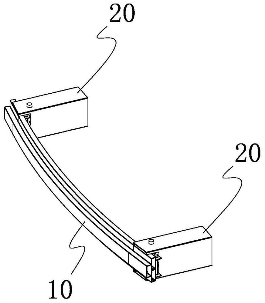
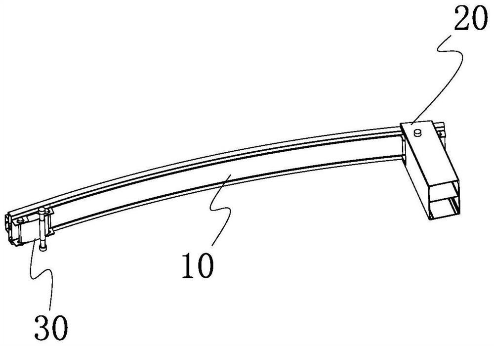
[0027] Please refer to figure 1 and figure 2 The automobile front anti-collision beam system provided by the present invention comprises a front anti-collision beam 10, two energy-absorbing boxes 20 respectively located at both ends of the front anti-collision beam 10, and an elastic connection assembly 30 connecting the front anti-collision beam 10 and the energy-absorbing box 20 .

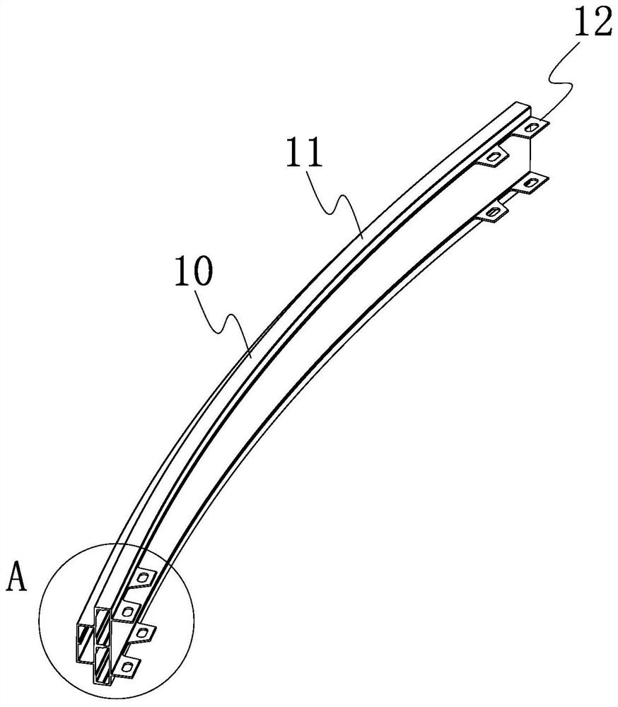
[0028] Please refer to image 3 and Figure 4 The front anti-collision beam 10 includes a slightly curved front anti-collision beam body 11 and a plurality of connecting protrusions 12 protruding from both ends of the inner concave surface of the front anti-collision beam body 11 .

[0029] The cr...


PUM


Abstract

An automobile front anti-collision beam system comprises a front anti-collision beam, two energy absorption boxes and elastic connecting assemblies for connecting the front anti-collision beam and theenergy absorption boxes; the two ends of one side of the front anti-collision cross beam are each provided with a plurality of connecting protruding blocks, and first connecting holes are formed in the middles of the connecting protruding blocks; an opening is formed in one end of each energy absorption box, protruding parts are formed on the upper portion and the lower portion of each opening, and second connecting holes are formed in the protruding parts; the elastic connecting assemblies are located at the openings, and each elastic connecting assembly comprises an elastic connecting sheet, two first connecting pins and a second connecting pin; two ends of the inner concave surface of each elastic connecting sheet are respectively connected with a first connecting hook ring, and the middle part of the outer convex surface of each elastic connecting sheet is connected with a second connecting hook ring; the first connecting pins penetrates through the first connecting hook rings andthe first connecting holes of the connecting lugs; and the second connecting pins penetrate through the second connecting hook rings and the second connecting holes of the energy absorption boxes. Reversible elastic deformation can be generated during light collision, the elastic connecting assemblies are convenient to replace during repairing, and the maintenance cost is reduced; during medium-high speed collision, peak stress can be effectively decomposed, joint cracking and failure are avoided, and the integrity of a force dispersion transmission system is maintained.

Description

technical field [0001] The invention relates to the field of automobile parts, in particular to an automobile front anti-collision beam system. Background technique [0002] The front anti-collision beam system of the vehicle needs to ensure that the low speed of 15km / h and below does not hurt itself, does not require maintenance, and reduces insurance costs. It can effectively protect pedestrians at a speed of 15-40km / h, and can effectively protect vehicles and vehicles at a speed of >40km / h. safety of passengers in the vehicle. In the early stage of a vehicle collision accident (generally within 15ms), the loss of kinetic energy of the vehicle is mainly absorbed by the collapse of the energy-absorbing box of the front anti-collision beam. If the connection between the front anti-collision beam and the energy-absorbing box cracks, the energy-absorbing box will easily become unstable, and the beam will roll over, which will affect the collapse and energy-absorbing effect...

Claims


Application Information

Patent Timeline
Patent Type & Authority Applications(China)
IPC IPC(8): B60R19/26B60R19/34
CPCB60R19/26B60R19/34B60R2019/247
Inventor 刘少华叶文强王立李莉宋腾辉
Owner ZHEJIANG GEELY HLDG GRP CO LTD
Why Eureka
Try Eureka