Screw rotor type surface profile error measurement instrument
An error measurement and surface profile technology, applied in measurement devices, instruments, optical devices, etc., can solve problems such as academic difficulties, complex compensation of probe ball radius errors, and inability to spiral profile measurement, and achieve three-dimensional reconstruction. , Improve the measurement accuracy and avoid the effect of probe radius compensation
- Summary
- Abstract
- Description
- Claims
- Application Information
AI Technical Summary
Problems solved by technology
Method used
Image
Examples
Embodiment Construction
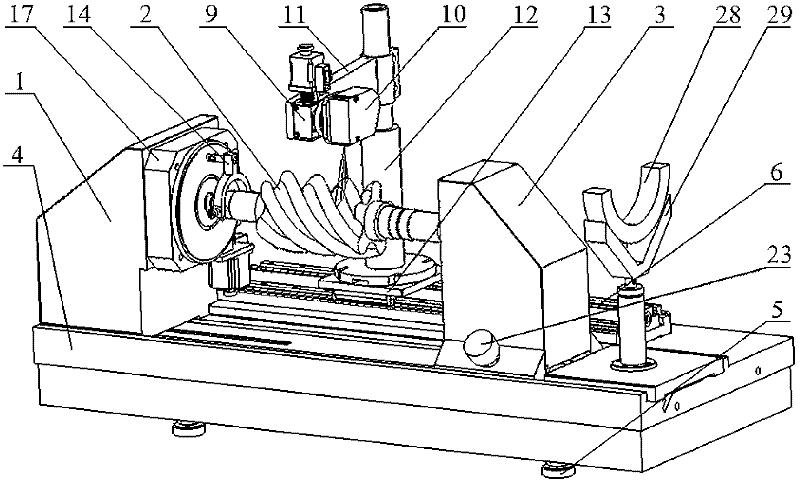
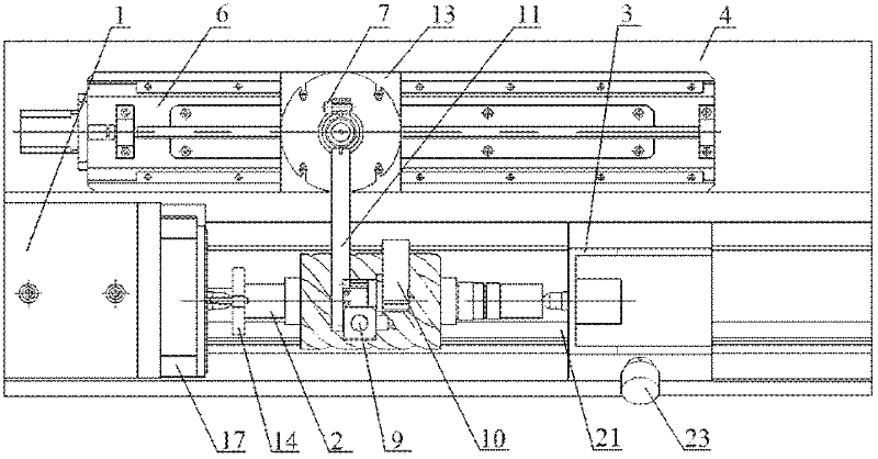
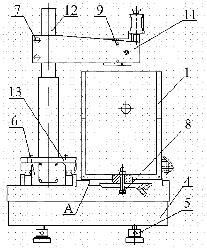
[0038] see figure 1 , figure 2 with image 3 , the front conical hole of the head frame 1 is precisely matched with the head frame thimble 16 as a conical surface, the head frame 1 is fixed on the base 4 with T-shaped screws 8, and the bottom of the base 4 is provided with a leveling foot 5 for adjusting the level of the base 4 The driving rod 15 is fixedly connected to the rotary table 19 through the external thread at the front end, the cylindrical hole on the upper surface of the shifting fork 14 is in clearance fit with the driving rod 15, and a pair of threaded holes are arranged at the lower end which are flush with the axial position of the rotor to be tested. The tightening screw 18 is screwed and passed through the threaded hole to clamp the measured helical rotor, so that the electric rotating table 17 drives the measured rotor 2 to rotate to realize precise indexing.
[0039] see Figure 5 with Image 6 The electric rotary table 17 fixedly arranged on the front...
PUM
 Abstract
Description
Claims
Application Information
 - R&D
- Intellectual Property
- Life Sciences
- Materials
- Tech Scout
- Unparalleled Data Quality
- Higher Quality Content
- 60% Fewer Hallucinations
Browse by: Latest US Patents, China's latest patents, Technical Efficacy Thesaurus, Application Domain, Technology Topic, Popular Technical Reports.
© 2025 PatSnap. All rights reserved.Legal|Privacy policy|Modern Slavery Act Transparency Statement|Sitemap|About US| Contact US: help@patsnap.com


