Multiturn rotary encoder

A rotary encoder and shaft technology, applied in the field of rotary encoders, can solve the problems of low working stability, damage to the code disc 1', and high installation accuracy requirements.

Inactive Publication Date: 2012-07-04
SANY HEAVY IND CO LTD (CN)
View PDF6 Cites 15 Cited by
  • Summary
  • Abstract
  • Description
  • Claims
  • Application Information

AI Technical Summary

Problems solved by technology

However, the multi-turn rotary encoder with the above-mentioned structure is composed of photoelectric code disc 1′ and two-pole magnet multi-turn components, etc., and its structure is complex and requires high installation accuracy; 1. In the case of vibration, the code disc 1′ is easily damaged, and the working stability is not high

Method used


Image

  • Multiturn rotary encoder
  • Multiturn rotary encoder
  • Multiturn rotary encoder

Examples


Embodiment Construction

[0035] The core of the present invention is to provide a multi-turn rotary encoder, which can realize accurate measurement of multi-turn rotation angles, and has the characteristics of simple structure and convenient operation, and can also prevent the code disc from being damaged by strong impact and strong vibration. damage, greatly improving the working stability of the multi-turn rotary encoder.

[0036] In order to enable those skilled in the art to better understand the technical solutions of the present invention, the present invention will be further described in detail below in conjunction with the accompanying drawings and specific embodiments.

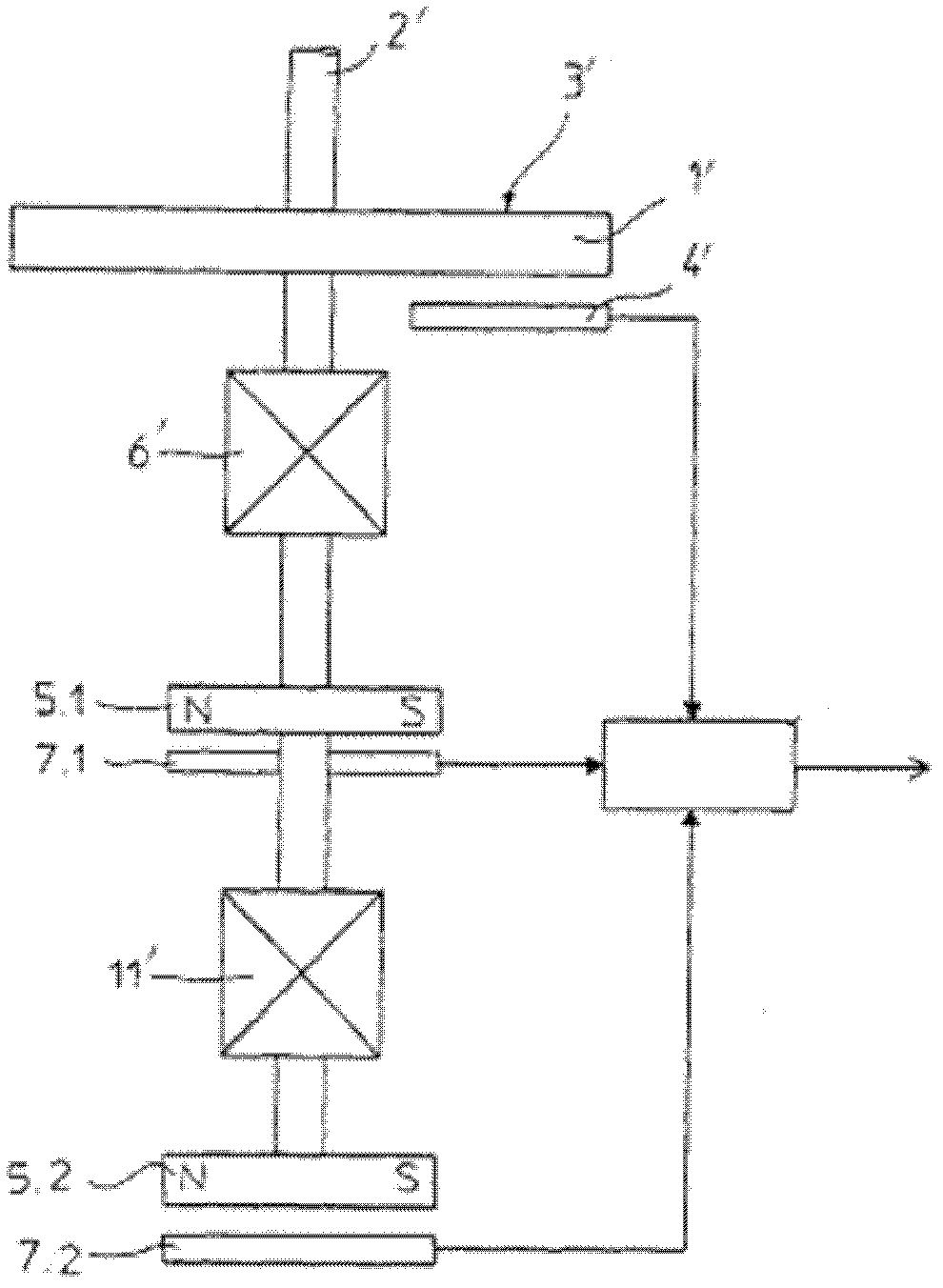
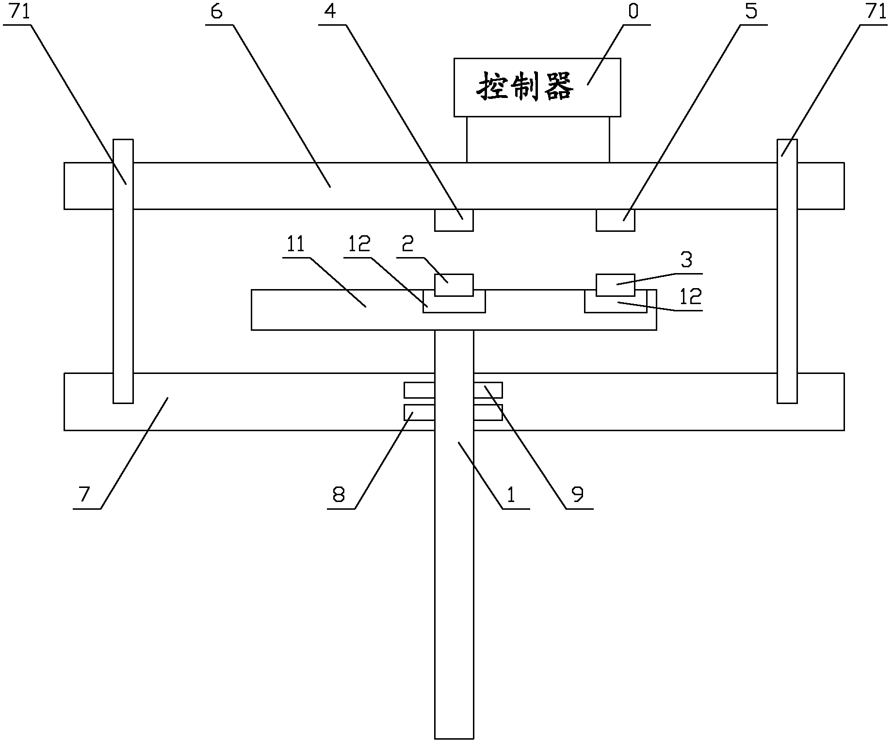
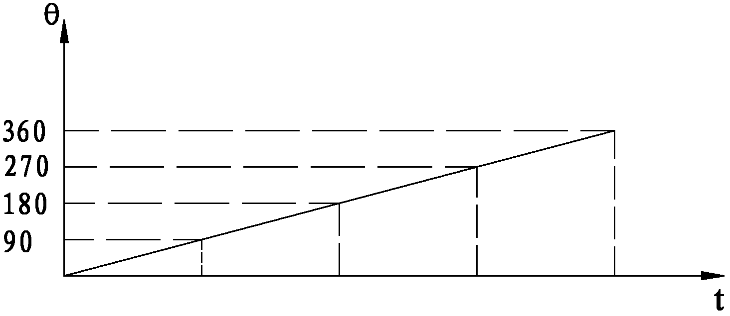
[0037] refer to Figure 2 to Figure 4 , figure 2 It is a structural schematic diagram of a specific embodiment of the multi-turn rotary encoder provided by the present invention; image 3 for figure 2 A graph of the signal output by the first inductive element varying with time; Figure 4 for figure 2 The graph of the ...


PUM


Abstract

The invention discloses a multiturn rotary encoder. The central part of the end surface of a rotary shaft (1) of the multiturn rotary encoder is provided with a first magnet (2), and the outer side of the first magnetic (2) is also provided with a second magnet (3); the multiturn rotary encoder also comprises a first sensing element (4), a second sensing element (5) and a controller (0), wherein the positions of the first sensing element (4) and the second sensing element (5) are fixed; the first sensing element (4) is arranged in the magnetic field range of the first magnet (2); within the time for the rotation of the rotary shaft (1) for a cycle, the second sensing element (5) is alternatively positioned in the magnetic field range of the second magnet (3) or is positioned out of the magnetic range of the second magnet (3); the controller is connected with the first sensing element (4) and the second sensing element (5), and is used for analyzing and processing the output signals of the first sensing element (4) and the second sensing element (5) and acquiring the detection result. The multiturn rotary encoder can measure the multiturn rotation angle of the rotary shaft, and has the characteristic of simple structure.

Description

technical field [0001] The invention relates to the technical field of rotary encoders, in particular to a multi-turn rotary encoder. Background technique [0002] The rotary encoder is a device used to measure the rotational speed. It mainly converts mechanical quantities such as angular displacement and angular velocity of the output shaft into corresponding electrical pulses through photoelectric conversion or electromagnetic conversion and outputs them in digital quantities. According to the detection range of the rotary encoder, the rotary encoder can be divided into a single-turn rotary encoder and a multi-turn rotary encoder. [0003] figure 1 It is a structural schematic diagram of a multi-turn rotary encoder disclosed in the patent document US6542088; the working principle and existing defects of this multi-turn rotary encoder are briefly introduced below. [0004] Such as figure 1 As shown, the multi-turn rotary encoder includes a rotating shaft that provides a ...

Claims


Application Information

Patent Timeline
Patent Type & Authority Applications(China)
IPC IPC(8): G01D5/244
CPCG01D5/347G01D5/244G01D5/245G01D5/145
Inventor 袁卫忠廖传伟王汉其
Owner SANY HEAVY IND CO LTD (CN)
Why Eureka
Try Eureka