Method for testing dielectric constant and loss angle tangent parameter of antenna cap material

A technology of loss tangent and dielectric constant, which is applied in measuring devices, measuring electrical variables, measuring resistance/reactance/impedance, etc., can solve problems such as heavy workload and high correlation

Inactive Publication Date: 2012-07-04
SHANGHAI RADIO EQUIP RES INST
View PDF4 Cites 6 Cited by
  • Summary
  • Abstract
  • Description
  • Claims
  • Application Information

AI Technical Summary

Problems solved by technology

This method not only has a large workload, but also has a large correlation between the test accuracy and the size of the tested piece.

Method used


Image

  • Method for testing dielectric constant and loss angle tangent parameter of antenna cap material
  • Method for testing dielectric constant and loss angle tangent parameter of antenna cap material
  • Method for testing dielectric constant and loss angle tangent parameter of antenna cap material

Examples


Embodiment Construction

[0025] Below in conjunction with example the present invention is described in further detail.

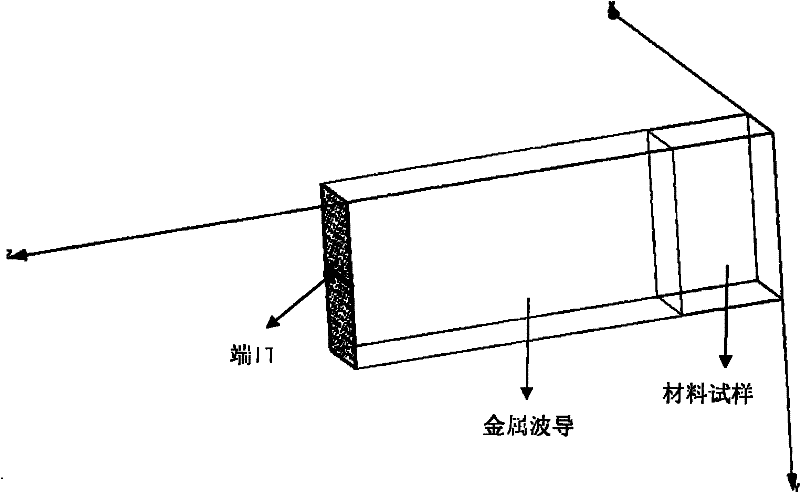
[0026] When f=10GHz, set the waveguide length for testing to an odd multiple of the half waveguide wavelength (take 3 times here):

[0027] l = λ g 2 . 3 = 30 1 - ( 30 22.86 × 2 ) 2 . 3 2 = 59.6 ( mm ) - - - ( 1 )

[0028] Through simulation, the initial phase of such a metal waveguide ...


PUM


Abstract

The invention provides a method for testing a dielectric constant and a loss angle tangent parameter of an antenna cap material. The method comprises the steps of: setting a testing waveguide length according to a testing frequency band, connecting the testing waveguide to a network analyzer, calibrating the network analyzer, testing an initial phase and a standing wave; placing a test block with wavelength of odd number times of that of a half waveguide or any length, measuring the phase and the standing wave by using the network analyzer; and scanning the dielectric constant of the material by using a parameter scanning function of an Ansoft HFSS (High Frequency Structure Simulator), setting the dielectric constant of the material to be 3.3-3.4 and the step length of the material to be 0.01, and obtaining a scanning simulation result of the phase. By adopting the invention, accurate testing of the dielectric constant and the loss angle tangent parameter of the antenna cap material is effectively improved, and the dielectric constant and the loss angle tangent (tan delta) parameter of a dielectric material can be obtained. The invention has the advantages of increasing working efficiency and reducing correlation of the testing precision and the size of a sheet to be tested.

Description

Technical field: [0001] The invention relates to the technical field of antennas, in particular to a method for accurately testing the microwave dielectric properties of dielectric materials used for radome. Background technique: [0002] The test of microwave dielectric properties of dielectric materials is an item in microwave testing. When using the short-circuit waveguide method for testing, the length of the tested piece must be an odd multiple of a quarter of the wavelength of the dielectric waveguide. [0003] At present, the usual practice is that when the dielectric constant of the measured dielectric material is not known, it is necessary to preliminarily determine the size of the tested dielectric material test piece, and after the test, determine the length of the test piece, which requires repeated tests , adjust the thickness of the sample, and gradually approach the exact value. This method not only has a large workload, but also has a large correlation betwe...

Claims


Application Information

Patent Timeline
Patent Type & Authority Applications(China)
IPC IPC(8): G01R27/26
Inventor 辛朋张漠杰
Owner SHANGHAI RADIO EQUIP RES INST
Why Eureka
Try Eureka