Punching head structure

A punching and pushing mechanism technology, applied in the field of punching head structure for metal parts, can solve the problems of easy deformation, easy deformation, rigidity and poor processing technology of metal parts

Pending Publication Date: 2021-03-23
SUZHOU MITAC PRECISION TECH
View PDF0 Cites 0 Cited by
  • Summary
  • Abstract
  • Description
  • Claims
  • Application Information

AI Technical Summary

Problems solved by technology

[0002] At present, metal parts need to be clamped by the chuck of the lathe when processing the punching head, but when the wall thickness of the metal part is thin, the rigidity and the processing technology are poor, it is easy to be clamped under the clamping force of the chuck. Deformation occurs, which affects the dimensional accuracy, shape and position accuracy of the workpiece
At the same time, due to the thinner wall thickness of the metal parts, the punching heat generated during the punching head processing operation will cause thermal deformation of the thin-walled metal parts, making it more difficult to guarantee and control the size of the metal parts
[0003] In view of this, it is necessary to develop a punching head structure to solve the problem that the metal parts are easily deformed by the chuck clamping of the current lathe, thus affecting the dimensional accuracy, shape and position accuracy of the workpiece

Method used


Image

  • Punching head structure
  • Punching head structure
  • Punching head structure

Examples


Embodiment Construction

[0033] In order to further illustrate the technical means and effects adopted by the present invention, a detailed description will be given below in conjunction with a preferred embodiment of the present invention and its accompanying drawings.

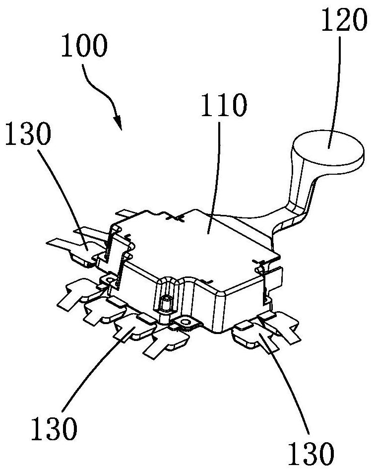
[0034] see figure 1 , figure 1 It is a schematic diagram of the structure of a metal part. The metal part 100 includes a part body 110 , a first head 120 and a second head 130 .

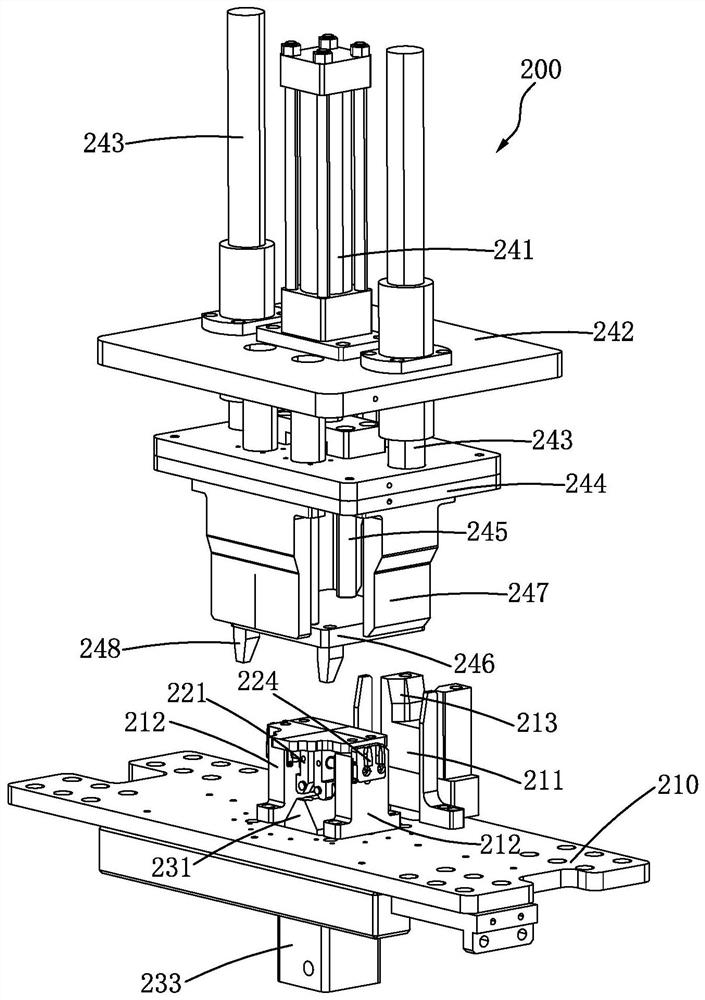
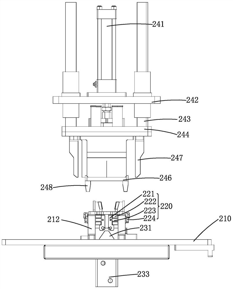
[0035] see figure 2 and image 3 , figure 2 It is a structural schematic diagram of a preferred embodiment of the punching head structure of the present invention, image 3 It is a front view of a preferred embodiment of the punch head structure of the present invention. In this embodiment, the present invention provides a punching head structure 200 for figure 1 The metal part 100 shown is for punching out the first material head 120 and the second material head 130, and the punching head structure 200 includes:

[0036] The fixed plate 210 has a...


PUM


Abstract

A punching head structure comprises a fixed plate, two clamping structures, an ejection structure, a punching structure and a control unit, wherein a through hole is formed in the middle of the fixedplate, and a first supporting piece and two second supporting pieces are arranged on the two sides of the through hole respectively; each clamping structure comprises an inner support block, a plurality of sliding rods, a first elastic element and a clamping block; the ejection structure comprises an ejection block, an ejection rod and a first pushing mechanism; the punching structure comprises asecond pushing structure, a guide sliding plate, two guide sliding shafts, a pushing plate, a plurality of second elastic elements, a pressing plate and a plurality of punching blades; and the controlunit is connected with the first pushing mechanism and the second pushing structure and controls the opening and closing of the first pushing mechanism and the second pushing structure. By utilizingthe punching head structure, the problem that at the present stage, a metal part is extremely prone to deformation due to clamping by a chuck of a lathe, and consequently the size precision, shape precision and position precision of a workpiece are affected is solved.

Description

【Technical field】 [0001] The invention relates to a punching head structure, in particular to a punching head structure for metal parts. 【Background technique】 [0002] At present, metal parts need to be clamped by the chuck of the lathe when processing the punching head, but when the wall thickness of the metal part is thin, the rigidity and the processing technology are poor, it is easy to be clamped under the clamping force of the chuck. Deformation occurs, thereby affecting the dimensional accuracy, shape and position accuracy of the workpiece. At the same time, due to the thinner wall thickness of the metal parts, the punching heat generated during the punching head processing operation will cause thermal deformation of the thin-walled metal parts, making it more difficult to guarantee and control the size of the metal parts. [0003] In view of this, it is necessary to develop a punching head structure to solve the problem that metal parts are easily deformed by the c...

Claims


Application Information

Patent Timeline
Patent Type & Authority Applications(China)
IPC IPC(8): B23D15/00B23D33/02
CPCB23D15/00B23D33/02
Inventor 胡传明
Owner SUZHOU MITAC PRECISION TECH
Why Eureka
Try Eureka