
Calibration Method for Synchronous Transmission of Symbols

A calibration method and symbol synchronization technology, applied in the field of communication, can solve the problems of voice pitch change, large audio distortion, lost words, etc.

Active Publication Date: 2014-10-22
SYNERTONE COMM TECH CO LTD
View PDF4 Cites 0 Cited by
  • Summary
  • Abstract
  • Description
  • Claims
  • Application Information

AI Technical Summary

Problems solved by technology

[0002] The carrier frequency stability of conventional transmitting stations is poor, generally 2ppm, that is, for the communication based on the trunking communication system with a frequency of 380MHz, a carrier frequency error of 760Hz can be generated
[0003] When the simulcast network communication system is working, multiple receivers in the overlapping area will receive audio signals from the same mobile station. If these signals are all forwarded, multiple audio signals will be superimposed, because the signal output from the selector is transmitted to the The link form or distance of each base station is different. The voice signal transmitted to the handheld radio through the transmitter of different simulcast base stations is affected by different path delays. There is a phase difference and amplitude of the audio signal received by the mobile station in the overlapping area. Fluctuation occurs, and the three parameters of delay, phase and amplitude are not well controlled, and there will be voice and voice distortion, large audio distortion, errors, and word loss. When two carriers enter the mobile station receiver at the same time, due to the receiver's The mixing effect can produce a maximum 1.52kHz beating interference signal, which will seriously affect the effect of the call

Method used


Image

  • Calibration Method for Synchronous Transmission of Symbols
  • Calibration Method for Synchronous Transmission of Symbols
  • Calibration Method for Synchronous Transmission of Symbols

Examples


Embodiment Construction

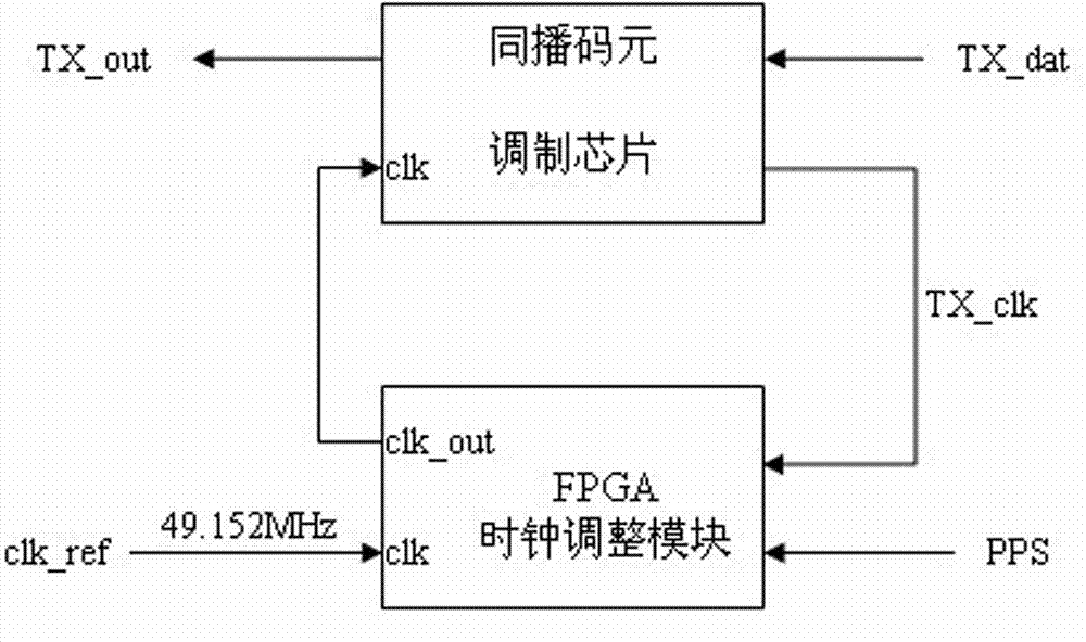
[0024] The calibration method for symbol synchronous transmission of the present invention comprises a simulcast symbol modulation chip and an FPGA clock adjustment module that generates an external reference clock source of the simulcast symbol modulation chip, and the clock adjustment module is provided with a system reference clock clk_ref.

[0025] The calibration method is mainly carried out in sequence as follows:

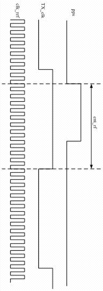
[0026] (1) The clock adjustment module uses the system reference clock clk_ref to count the time period from the time of receiving the PPS signal transmitted by GPS to the moment before the next PPS signal, and records the counted value as cnt_1s, and defines the system reference clock at the same time Theoretical standard frequency value const_1s;

[0027] (2) When the simulcast symbol modulation chip receives the transmit symbol signal TX_dat, it outputs the symbol transmit clock TX_clk to the clock adjustment module, and the clock adjustment module uses th...


PUM


Abstract

The invention provides a calibration method for code element synchronization emission, which comprises a simulcasting code element modulation chip and a clock adjusting module generating an external reference clock source of the simulcasting code element modulation chip. The calibration method particularly and sequentially comprises that the clock adjusting module counts received pulse per second (PPS) signals, the simulcasting code element modulation chip receives code element signals and outputs clock signals to the clock adjusting module which counts the code element signals, a fractional frequency proportion value for conducting fractional frequency output on a systematical reference clock is set, logic operation is conducted on standard frequency value of the systematical reference clock and two recorded count values to obtain deviate of the systematical reference clock, accumulation of the deviate delta is conducted and the accumulated value is judged whether exceeding the fixing value or not to conduct corresponding operation of the fractional frequency proportion value, according to the fractional frequency proportion value output signals, the clock adjusting module serve as the clock source of the simulcasting code element modulation chip. The calibration method can improve reliability of communication, timely adjust code element emission signals of simulcasting code element modulation chip, and achieve synchronization of code element emission.

Description

technical field [0001] The invention belongs to the field of communication, and relates to a method for synchronizing symbols transmitted by a base station in wireless communication. Background technique [0002] The carrier frequency stability of conventional transmitting stations is relatively poor, generally 2ppm, that is, a carrier frequency error of 760Hz can be generated for communications based on trunking communication systems with a frequency of 380MHz. [0003] When the simulcast network communication system is working, multiple receivers in the overlapping area will receive audio signals from the same mobile station. If these signals are all forwarded, multiple audio signals will be superimposed, because the signal output from the selector is transmitted to the The link form or distance of each base station is different. The voice signal transmitted to the handheld radio through the transmitter of different simulcast base stations is affected by different path del...

Claims


Application Information

Patent Timeline
Patent Type & Authority Patents(China)
IPC IPC(8): H04W56/00
Inventor 王浙安张延涛高文俊
Owner SYNERTONE COMM TECH CO LTD
Learn More