Load driving device and system

一种负载驱动、负载单元的技术,应用在电路领域,能够解决调整管损耗大、接线复杂、驱动器发热等问题,达到节约成本、降低复杂度、接线简单的效果

Active Publication Date: 2012-07-04
INVENTRONICS HANGZHOU
View PDF4 Cites 13 Cited by
  • Summary
  • Abstract
  • Description
  • Claims
  • Application Information

AI Technical Summary

Problems solved by technology

[0005] First of all, in order to facilitate the minimum value sampling circuit in the driver to sample the voltage from the subsequent circuit, the linear adjustment current limiting circuit 203 in each LED branch usually needs to be packaged inside the driver, and adjust when the voltage difference between multiple LED branches is large. The tube loss is large, which leads to serious heating of the driver; moreover, the driver is generally placed inside the LED lamp, close to the LED light source, the temperature will be higher, which seriously affects the reliability of the driver;
[0006] Secondly, the output voltage control circuit 204 of the output voltage adjustable voltage source 201 of the previous stage needs to sample the voltage from the subsequent stage circuit composed of each LED and the linear adjustment current limiting circuit 203, so that the output voltage adjustable voltage source of the previous stage The wiring between 201 and the subsequent circuit is complicated; moreover, when an open-circuit fault occurs in a certain LED load, the drain voltage of the line adjustment tube is zero. Therefore, it is necessary to add an additional open-circuit protection for each LED load to ensure that in this case The normal operation of other LED loads that have not failed, which further increases the complexity of the circuit

Method used


Image

  • Load driving device and system
  • Load driving device and system
  • Load driving device and system

Examples


Embodiment Construction

[0061] Hereinafter, specific implementations of the load driving device and system according to the embodiments of the present invention will be described in detail in conjunction with the accompanying drawings.

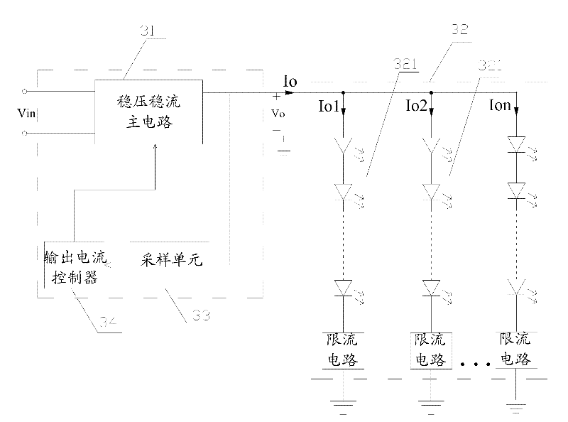
[0062] The load driving device of the embodiment of the present invention includes the following structure:

[0063] The voltage-stabilizing and current-stabilizing main circuit is used to perform voltage conversion on the input voltage under the control of the output current controller, and provide electric energy to the load unit of the subsequent stage;

[0064] The sampling unit is connected to the output terminal of the main circuit for voltage and current stabilization, and is used for sampling the output characteristic parameters of the main circuit for voltage and current stabilization, and sending the sampled signal to the output current controller;

[0065] Output current controller, the input terminal is connected with the output terminal of the sampling u...


PUM


Abstract

The invention discloses a load driving device, comprising a voltage-stabilizing and current-stabilizing main circuit, a sampling unit and an output current controller, wherein the voltage-stabilizing and current-stabilizing main circuit is used for converting input voltage and providing electric energy for a post-stage load unit under the control of the output current controller, the sampling unit is connected with the output terminal of the voltage-stabilizing and current-stabilizing main circuit and is used for sampling output characteristic parameter of the voltage-stabilizing and current-stabilizing main circuit; and the output current controller is used for controlling a current-limiting point of the voltage-stabilizing and current-stabilizing main circuit, a steady state operating point of the voltage-stabilizing and current-stabilizing main circuit is determined according to regulating direction of the current-limiting point and variation of the output characteristic parameter of the voltage-stabilizing and current-stabilizing main circuit before and after being regulated, and the voltage-stabilizing and current-stabilizing main circuit is controlled to operate at the steady state operating point. The load driving device disclosed by the invention can improve reliability of a driver; meanwhile, complexity of the circuit can be reduced. The invention also discloses a control method and device.

Description

technical field [0001] The invention relates to the field of circuits, in particular to a load driving device and system. Background technique [0002] Most of the existing light-emitting diode (LED) lamps refer to the lamp structure and design of traditional gas discharge lamps and tungsten lamps, and also follow the traditional idea of ​​configuring a driver for a light source in the driving scheme, and the traditional single-channel Or multiple output AC / DC conversion technology. Such as figure 1 As shown, a lamp includes a light source and a driver, and the lamp is controlled by a power distribution switch. Among them, such as figure 1 As shown, the driver is arranged inside the lamp, close to the light source. [0003] specific, figure 2 A specific circuit structure of an LED lamp is given in , wherein, the output voltage adjustable voltage source 201 of the previous stage passes through the minimum value sampling circuit 202, and the multi-line linear adjustment ...

Claims


Application Information

Patent Timeline
Patent Type & Authority Applications(China)
IPC IPC(8): H05B37/02H05B44/00
CPCY02B20/347H05B33/0827H05B33/0815H05B45/46Y02B20/30H05B45/3725
Inventor 葛良安华桂潮姚晓莉柳杨
Owner INVENTRONICS HANGZHOU
Why Eureka
Try Eureka