
Stainless steel wire annealing and heating process system

A technology of stainless steel wire and process system, which is applied in the field of annealing technology, can solve the problems of large variable factors of protective gas, easy explosion of hydrogen gas, high cost, etc., reduce cooling consumption time and heat source, good metallographic structure, and high production efficiency Effect

Inactive Publication Date: 2022-05-27
江苏铂宝焊材有限公司
View PDF0 Cites 0 Cited by
  • Summary
  • Abstract
  • Description
  • Claims
  • Application Information

AI Technical Summary

Problems solved by technology

However, due to the explosive nature of hydrogen, ammonia decomposition gas is generally used in the industry at present, resulting in a large variable factor in the purity of the protective gas, which requires more airtight control in the design and use of equipment , to ensure that the concentration of the protective gas meets the requirements and achieve the purpose of recrystallization bright annealing
However, the equipment used for ammonia decomposition gas is limited to the annealing furnace, the cost is high, and the cycle is long

Method used


Image

  • Stainless steel wire annealing and heating process system
  • Stainless steel wire annealing and heating process system

Examples


Embodiment 1

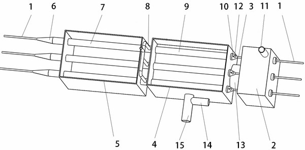
[0029] like figure 1 The shown stainless steel wire annealing and heating process system has a plurality of stainless steel wires arranged in parallel. According to the walking route, each stainless steel wire passes through its own oven steel pipe section, exposed section, wire feeding steel pipe section, annealing furnace steel pipe section, cooling Pipe section, wire outlet pipe section.

[0030] The wire feed steel pipe section, the annealing furnace steel pipe section, the cooling pipe section and the wire outlet pipe section are interconnected pipelines.

[0031] A reducing gas pipeline is connected between the steel pipe section of the annealing furnace and the cooling pipe section. The entrance of the wire feeding steel pipe section has an opening for the outflow of reducing gas and the entry of stainless steel wire. It can be used for the outflow of stainless steel wire, but not for the outflow of reducing gas.

Embodiment 2

[0033] like figure 2 As shown, using the device in the first embodiment, the pipe wall of the wire-feeding steel pipe section is preset with a plurality of downward air outlet holes arranged along the length direction as openings for the reducing gas to be discharged step by step, and the air is mixed with the air. Oxygen in the reactor is ignited at the outlet to generate heat, heating the tube wall, so that the stainless steel wire is heated for the second time, and the stainless steel wire is instantly heated online to the second stage temperature required for annealing.

[0034] By controlling the speed of the steel wire, the diameter data of the wire feeding tube, the diameter data of the steel wire, the pressure or flow of the alkane (especially butane) gas, etc., the three sections of the steel wire can be controlled to be heated section by section, and the final temperature reaches the required annealing temperature. temperature. Next, the wire is pulled out after bein...


PUM

PropertyMeasurementUnit
diameteraaaaaaaaaa
lengthaaaaaaaaaa
diameteraaaaaaaaaa

Abstract

According to a stainless steel wire walking route, each stainless steel wire sequentially penetrates through a drying oven pipe section, an exposed section, a wire inlet pipe section, an annealing furnace pipe section, a cooling pipe section and a wire outlet pipe section of the stainless steel wire according to the walking route; in addition, reducing gas is communicated with the joint of the annealing furnace pipe section and the cooling pipe section and flows out towards the opening of the wire feeding pipe to be combusted, and the stainless steel wire is instantly heated; and the subsequent stainless steel wire annealing furnace section is heated to the annealing temperature, cooled by the cooling pool and discharged from the wire outlet pipe. The stainless steel wire annealing equipment is simple and ingenious in structure and low in manufacturing cost and use cost, the reducing gas has multiple combination functions, the stainless steel wire heating efficiency is high, and the metallographic structure is good.

Description

technical field [0001] The invention relates to an annealing technology in the process of wire drawing. Background technique [0002] The heat treatment of stainless steel is generally solution heat treatment in an annealing furnace, which is usually called "annealing", and the temperature range is 1040~1120 °C. The annealing atmosphere generally uses pure hydrogen as the annealing atmosphere, and the purity of the atmosphere is preferably more than 99.99%. If the other part of the atmosphere is an inert gas, the purity can also be lower, but it must not contain too much oxygen and water vapor. [0003] The invention of 2014107925319 provides an annealing process of raw wire for stainless steel welding wire. Before drawing, the coil of the raw wire is annealed and heat treated in an annealing furnace, so that the furnace temperature is gradually raised to the temperature required by the process, and then cooled down and cooled. This technology can be used as the reference c...

Claims


Application Information

Patent Timeline
Patent Type & Authority Applications(China)
IPC IPC(8): C21D1/26C21D1/74C21D9/573
CPCC21D1/26C21D1/74C21D9/5732C21D9/561C21D9/0062Y02P10/20
Inventor 周新春蔡小栋周焕
Owner 江苏铂宝焊材有限公司
Learn More