
Drive device

A technology for driving equipment and driving shafts, used in driving devices, precision positioning equipment, metal processing equipment, etc., can solve the problems of expensive manufacturing, large structure, etc., achieve compact structure type, promote structure type, prevent tilting or jamming. Effect

Active Publication Date: 2012-07-04
ZEITFRACHT GMBH & CO KGAA
View PDF8 Cites 1 Cited by
  • Summary
  • Abstract
  • Description
  • Claims
  • Application Information

AI Technical Summary

Problems solved by technology

The known solutions have a relatively large design and provide a plurality of cooperating toothings which are functionally connected in succession for the drive of the cutter head and the machining tool, so that in the known solutions in order to realize the The precision required for the tool turret requires rather expensive manufacturing

Method used


Image

  • Drive device
  • Drive device
  • Drive device

Examples


Embodiment Construction

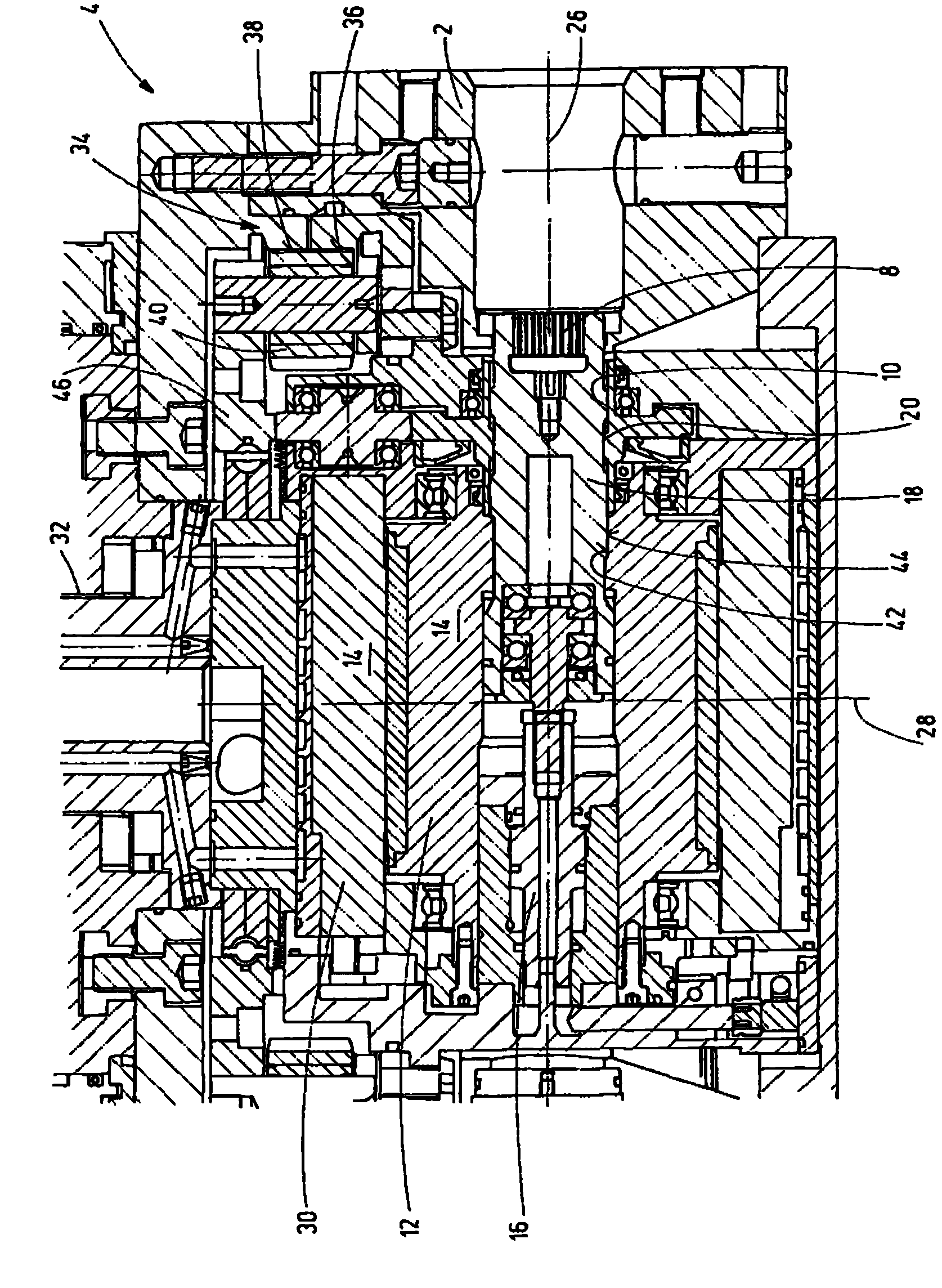
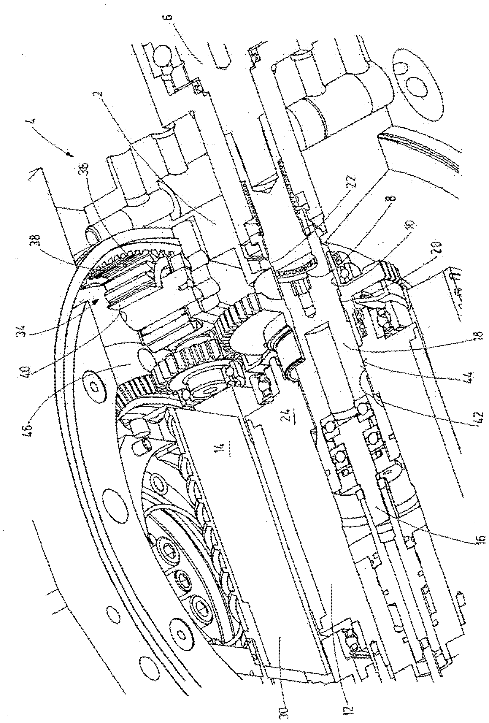
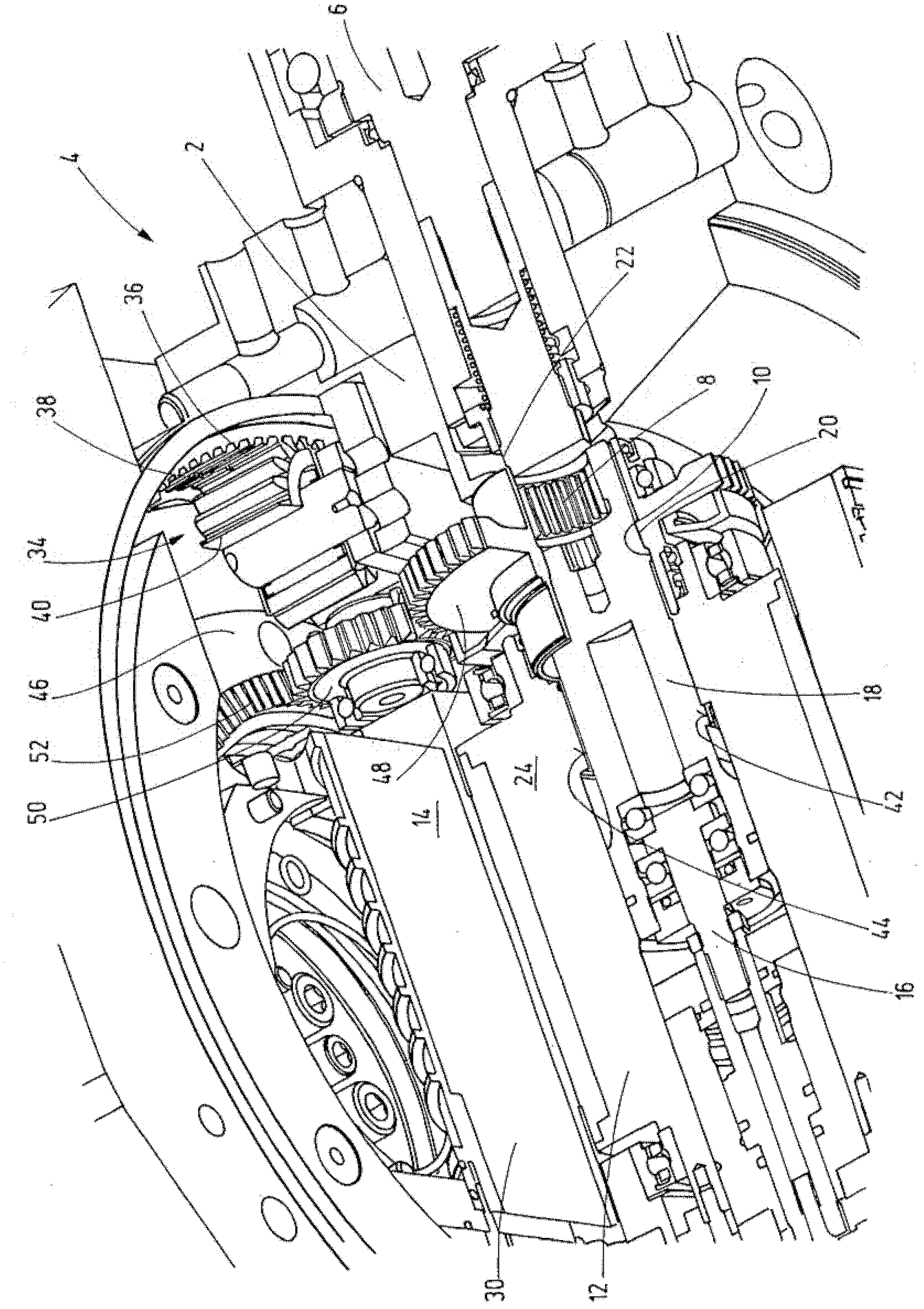
[0028] exist figure 1 In the shown drive device for selectively driving the cutter head 2 of the tool turret 4 and at least one machining tool (not shown), the driving is effected by means of two drive mechanisms 8, 10, the machining tool being driven by means of Holding device 6 (see figure 2 ) can be fixed on the cutter head 2, and the two drive mechanisms can be driven by a common drive device 14 with a drive shaft 12. The drive mechanism 8 , 10 is connectable to the output mechanism 20 , 22 via a coupling device 18 , which can be controlled in each case by at least one actuating device 16 . Here, the output mechanism 20 is used to drive the cutter head 2 , while the output mechanism 22 is used to drive the machining tool. The drive device 14 is arranged inside the cutterhead 2 together with the output mechanisms 20 , 22 .

[0029] The respective drive mechanism 20 , 22 is arranged between the drive device 14 and the machining tool to be driven in a receiving space 24 i...


PUM


Abstract

The invention relates to a drive device for alternatively driving a tool disk (2) of a tool turret (4) or at least one machining tool, which can be fastened to the tool disk (2) by means of a retaining unit (6), by means of two drive means (8, 10), which can be driven by a common drive unit (14) having a drive shaft (12), the drive means (8, 10) being connectible to output means (20, 22) by means of a coupling unit (18) that can be controlled by at least one actuating unit (16), the output means being used alternatively to drive the tool disk (2) or the machining tool, the drive device being characterized in that at least the drive unit (14) is arranged inside the tool disk (2) together with the drive means (8, 10).

Description

technical field [0001] The invention relates to a drive device for selectively driving a cutter head of a tool turret and at least one machining tool by means of two drive mechanisms, which can be fixed on the cutter head by means of a holding device, said two drive mechanisms The mechanisms can be driven by a common drive having a drive shaft, wherein the drive mechanism can be connected via a coupling device, which can be controlled accordingly by at least one actuating device, to a driven mechanism for driving the cutting disc or machining tool. Background technique [0002] The drive device for the tool turret here is used in particular when, by means of a common drive, the drive of the rotating machining tool is to be realized in addition to the pivoting of the cutter head for the selection of the machining tool required for the current machining process. The industry is manufacturing. [0003] No. 7,475,463 B1 discloses a cutting machine tool (cutting machine) in whic...

Claims


Application Information

Patent Timeline
Patent Type & Authority Applications(China)
IPC IPC(8): B23Q5/04B23Q16/02
CPCB23Q5/04B23Q16/025B23Q2220/002Y10T29/5155
Inventor D·林德J·施蒂费尔
Owner ZEITFRACHT GMBH & CO KGAA
Learn More