Fan motor and air conditioner with same

A fan motor and three-phase motor technology, which is applied in mechanical equipment, electrical components, machines/engines, etc., can solve the problems of larger fan motors and larger housings, and achieve the effect of improving design freedom and large ventilation channels

Inactive Publication Date: 2012-07-04
MITSUBISHI ELECTRIC CORP
View PDF7 Cites 17 Cited by
  • Summary
  • Abstract
  • Description
  • Claims
  • Application Information

AI Technical Summary

Problems solved by technology

[0006] However, such a fan motor (for example, refer to Patent Document 1) can reduce the size of the fan hub, but since the stator is arranged on the entire outer peripheral side of the fan, there are problems in that the casing becomes larger and the fan motor itself becomes larger.

Method used


Image

  • Fan motor and air conditioner with same
  • Fan motor and air conditioner with same
  • Fan motor and air conditioner with same

Examples


no. 1 approach

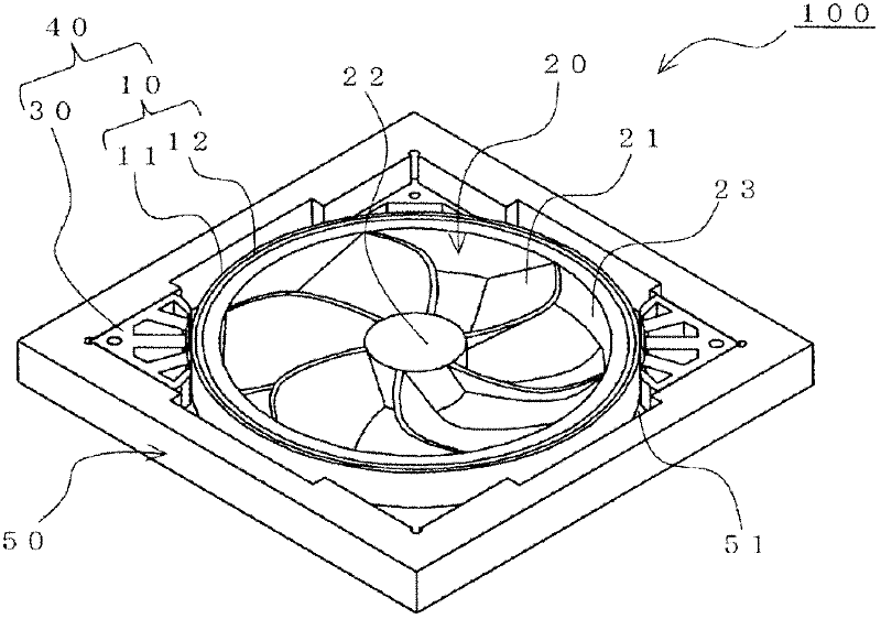
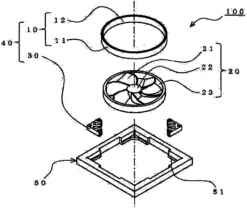
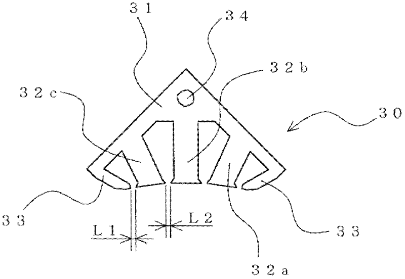
[0025] figure 1 It is an external perspective view showing the fan motor according to the first embodiment of the present invention. figure 2 is an assembled perspective view of the fan motor. in addition, image 3 is a front view showing the stator of the fan motor.

[0026] The fan motor 100 is an axial fan structure, and is composed of a blade portion 20 , a motor 40 having a rotor 10 and a stator 30 , and a housing 50 .

[0027] The casing 50 has a substantially quadrilateral frame shape, and the blade portion 20 is provided inside.

[0028] The blade portion 20 has a fan hub portion 22 and a plurality of blades 21 . Fan hub portion 22 serves as the rotation center of blade portion 20 , and blade 21 is formed on its outer peripheral portion. In addition, a substantially annular ring 23 is formed on the outer peripheral portion of the blade 21 . Blade portion 20 (blade 21 , fan hub portion 22 , and ring 23 ) is integrally formed of, for example, a resin material. In...

no. 2 approach

[0057] For example, the arrangement position of the stator 30 and the formation position of the auxiliary teeth 33 may be set as follows. In addition, about the item which is not described especially in 2nd Embodiment, it is the same as 1st Embodiment.

[0058] Figure 5 It is a front view showing the fan motor of the second embodiment of the present invention.

[0059] In the fan motor 101 of the second embodiment, stators (one stator 30 , three stators 30 a ) are provided at all corners (four locations) of the casing 50 . In addition, among these stators, one stator 30 is provided with auxiliary teeth 33 at both ends thereof, and the other three stators 30a are not provided with auxiliary teeth. These points are the differences between the fan motor 101 of the second embodiment and the fan motor 100 of the first embodiment, and the other structures are the same.

[0060] That is, the fan motor 101 cancels and reduces the cogging effect generated by the ends of the stator ...

no. 3 approach

[0064] In addition, the arrangement position of the stator 30 and the formation position of the auxiliary teeth 33 may be set as follows, for example. In addition, in 3rd Embodiment, the item which is not described especially is the same as 1st Embodiment or 2nd Embodiment.

[0065] Figure 6 It is a front view showing the fan motor of the third embodiment of the present invention. in addition, Figure 7 is a front view showing the stator.

[0066] In the fan motor 102 of the third embodiment, the auxiliary teeth 33 are provided only at one end of the stator 30b. Other configurations are the same as those of the fan motor 100 of the first embodiment.

[0067] More specifically, among the stators 30b provided at opposite corners of the casing 50, one stator 30b ( Figure 6 The upper right stator 30b) in FIG. 2 is provided with auxiliary teeth 33 adjacent to the W-phase teeth 32c. In addition, among the stators 30b provided at opposite corners of the casing 50, the other s...


PUM


Abstract

Provided are a fan motor having an increased degree of freedom in design obtained with an increase in the size of the fan motor minimized, and an air conditioner provided with the fan motor. A fan motor (100) provided with: a blade section (20); a motor (40) which has a rotor (10) provided on the outer periphery of the blade section (20) and also has a stator (30) provided on the outer peripheral side of the rotor (10) and having teeth (32) on the inner peripheral surface thereof; and a housing (50) which is provided so as to cover the outer peripheral side of the stator (30) and the rotor (10). The housing (50) is a polygon, the stator (30) is provided to at least one corner of the housing (50), and some or all of the stators (30) each have an auxiliary tooth (33) provided to an end thereof.

Description

technical field [0001] The present invention relates to a fan motor and an air conditioner including the fan motor. Background technique [0002] For the existing air conditioner, in order to make the indoor unit thinner and more compact, it is proposed to use a propeller fan in the fan unit. Such a propeller fan is provided with a fan hub as a center of rotation, and a blade having blades formed from the fan hub toward the outer peripheral side. In addition, a motor for rotating the blade is provided on the fan hub. That is, the motor is an outer rotor type, and blades are provided on the rotor side (rotation side). For this reason, if the motor is enlarged, the size of the fan blades arranged outside the motor will be limited, which will block the ventilation passage. Therefore, there are problems that a sufficient air volume cannot be obtained, the design freedom of the blade portion is small, and the power of the fan is reduced. In addition, if the size of the motor ...

Claims


Application Information

Patent Timeline
Patent Type & Authority Applications(China)
IPC IPC(8): H02K1/18H02K1/10H02K5/04
CPCH02K1/148F04D29/326H02K1/185F04D25/066
Inventor 森刚井上正哉山田彰二福井智哉
Owner MITSUBISHI ELECTRIC CORP
Why Eureka
Try Eureka