Sowing plow

A seeder and seeding ditch technology, applied in the direction of sowing, sowing seeder, application, etc., can solve the problem of reducing the spacing of seeding grooves

Inactive Publication Date: 2012-07-11
JANG JADONGHWA
View PDF6 Cites 9 Cited by
  • Summary
  • Abstract
  • Description
  • Claims
  • Application Information

AI Technical Summary

Problems solved by technology

However, due to the ridges formed on the sides of the seeding grooves, the pitch of the seeding grooves is rarely reduced to the desired size

Method used


Image

  • Sowing plow
  • Sowing plow
  • Sowing plow

Examples


no. 2 example

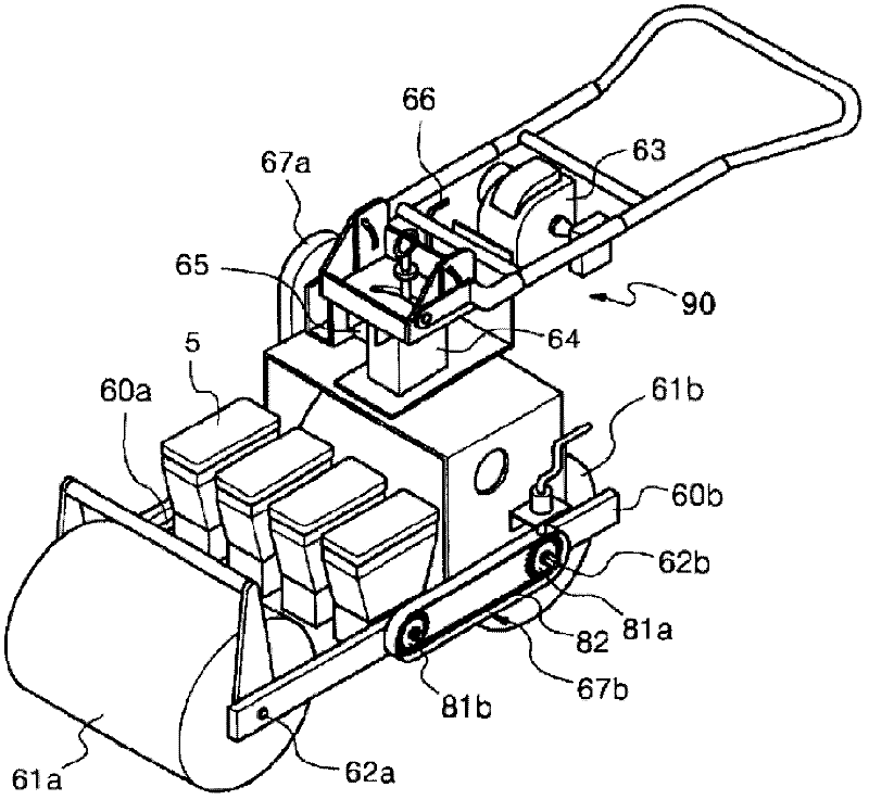
[0079] Figure 14 is a perspective view of a transmission unit of a planter with a one-touch detachable hopper depicting a second embodiment of the present invention, Figure 15 is a schematic diagram of a planter with a one-touch detachable hopper describing a second embodiment of the present invention. To describe this in detail, the first roller 61a and the second roller 61b are driven by an engine 63, wherein the driving force from the engine 63 is transmitted via a speed reducer 64, a first clutch 65 for selectively transmitting rotational driving force, and power transmission The device 67a rotates the second roller shaft 62b of the second roller 61b provided at the rear. The second power transmission device 67b is configured to connect the first roller shaft 62b and the first roller shaft 62a in a transmission manner, and the third power transmission device 67c is configured to connect the first roller shaft 62a and the first roller shaft 62a in a rotatable manner. Th...

no. 3 example

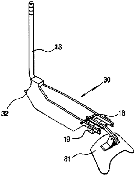
[0090] Figure 16 is a schematic diagram describing a third embodiment of the present invention of a planter with a one-touch detachable hopper, which is manually driven.

[0091] The first roller 61a and the second roller 61b are configured to be rotatable by a driving force generated when the first roller 61a and the second roller 61b are pushed or pulled forward. The driving force is directly transmitted to the hopper installation unit driving shaft 52 through the fourth transmission chain 134 wound on the first roller shaft 62a.

[0092] With this arrangement, the first sprocket 53a, the second sprocket 53b, and the second transmission chain 54 of the hopper installation unit 1 mounted on the drive shaft are driven, so that the driven gear 43 of the hopper 5 loaded and unloaded by the latch 57 Rotation, thus realizing sowing or fertilizing.


PUM


Abstract

The invention provides a sowing machine, comprising a hopper mounting unit, a hopper, and a seed discharge roller. When mounting the hopper on the hopper mounting unit, an assembly shaft in the front end of the hopper is inserted into an assembling slot, then the hopper is rotated backward around the assembly shaft, making a follower gear contact with a pin of a transmission chain, so that the transmission chain is meshed with the follower gear, and the hopper mounting unit one-to-one corresponds to the hopper with multiple thereof side by side. With the above structure, the mounting of the hopper becomes easy, and under the circumstance of sowing to a plurality of grooves, with the above hopper mounting structure, a plurality of hoppers can be mounted side by side at given width. Thus, the number of sowing groove in unit area is increased so that the seeding rate is increased.

Description

technical field [0001] The present invention relates to a sowing machine, which is designed to form a sowing groove in the soil, spread seeds into the sowing groove, and cover the sowing groove with soil at the same time, and the sowing machine has the function of being installed through a hopper A one-touch detachable hopper structure on which the structure is detachably mounted to regularly discharge preset amounts of seeds, fertilizers and pesticides. More specifically, the present invention relates to a planter having a one-touch detachable hopper and designed to be driven forward by an engine or manually, wherein the hopper engages and is driven by a chain Can be easily installed on and separated from the hopper installation unit by inserting the loading and unloading lever at the front end of the hopper into the assembly groove of the hopper installation unit, the chain is associated with the drive shaft of the hopper installation unit, therefore, Not only can the hoppe...

Claims


Application Information

Patent Timeline
Patent Type & Authority Applications(China)
IPC IPC(8): A01C7/08
CPCA01C7/206A01C7/127
Inventor 张在洙
Owner JANG JADONGHWA
Why Eureka
Try Eureka