Method for preventing split membrane bio-reactor (MBR) flat membrane pollution

A flat-plate membrane and split-type technology, applied in chemical instruments and methods, membrane technology, semi-permeable membrane separation, etc., can solve problems affecting sludge properties, increase ton water treatment cost, and remove surface adsorbates, etc., to achieve enhanced shear Cutting force, prolonging the interval time, improving the cleaning effect

Active Publication Date: 2012-07-11
GUANGZHOU EP ENVIROMENTAL ENG
View PDF3 Cites 16 Cited by
  • Summary
  • Abstract
  • Description
  • Claims
  • Application Information

AI Technical Summary

Problems solved by technology

Due to the strong adsorption capacity of these high-molecular organic matter, the shear force formed by aeration is not enough to remove the surf

Method used


Image

  • Method for preventing split membrane bio-reactor (MBR) flat membrane pollution
  • Method for preventing split membrane bio-reactor (MBR) flat membrane pollution
  • Method for preventing split membrane bio-reactor (MBR) flat membrane pollution

Examples


Embodiment 1

[0041] Embodiment 1 Method 1 for preventing fouling of split-type MBR flat-panel membranes

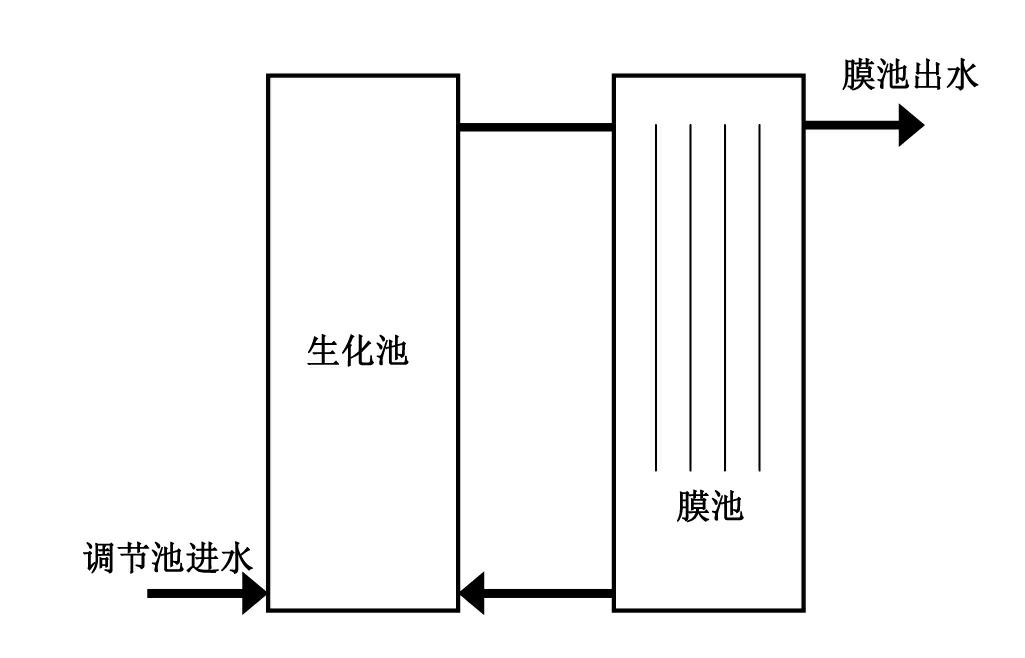
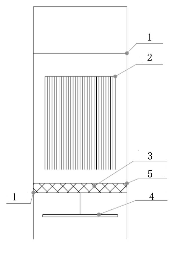
[0042] A separate membrane bioreactor, which consists of two parts: a biochemical pool and a membrane pool, and the membrane module box is placed in the membrane pool (see figure 1 ). Such as figure 2 As shown, the present invention arranges a layer of screen 1 at the bottom and top of the membrane module box, and a flat membrane group 2 is placed in the box between the two layers of screens, and a granular filler 3 is added in the box between the two layers of screens. , the diameter of the particle filler is larger than the mesh diameter of the screen, the aeration pipe 4 is placed under the bottom screen, and the membrane module box is provided with a filler replacement window 5, which is used for filler replacement and screen cleaning.

[0043] In this embodiment, the mesh diameter of the screen is 2mm; the particle filler used is round ceramsite with a density of 1.1kg / m 3 ...

Embodiment 2

[0052] Embodiment 2 Method 2 for preventing fouling of split-type MBR flat-panel membranes

[0053] In this example, for the separate membrane bioreactor, the mesh diameter of the screen is 1.5mm; the particle filler used is round fruit shell filler (mainly hickory shell), and the density range is 1.1~1.25 kg / m 3 , with an average density of 1.15 kg / m 3 , with a diameter of 1.8~3mm and an average diameter of 2.2mm. The total volume of the filler is 20% of the volume of the box between the upper and lower screens; the flat membrane group used, the gap between each flat membrane is 20mm. The bottom aeration adopts high-pressure aeration, which reduces the intake air volume and increases the intake air pressure. Increase the circulation and agitation of the aeration to the filler.

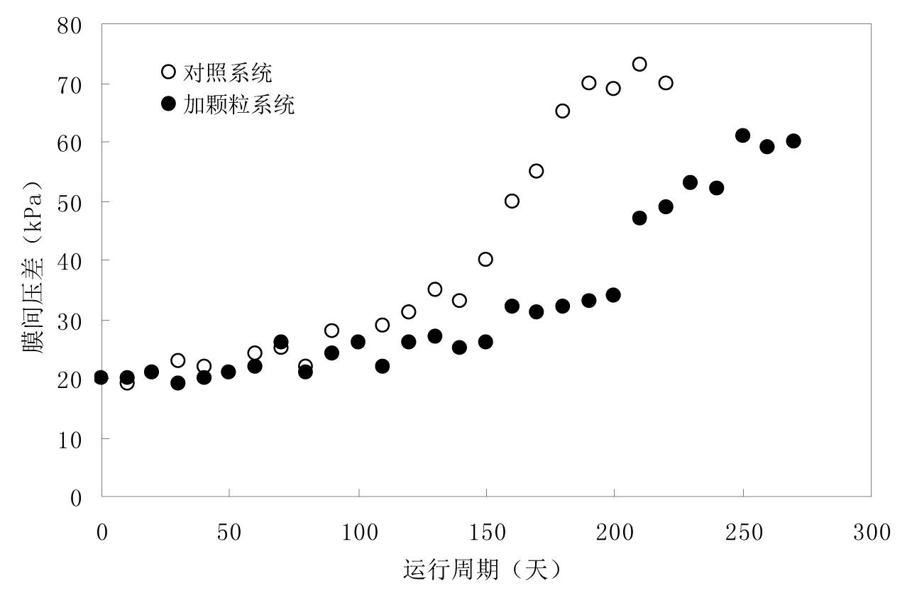
[0054] The pressure difference between the membranes under the condition of the same permeate flow in the membrane bioreactor

[0055] Depend on Figure 6 It can be seen from the figure that ...


PUM

PropertyMeasurementUnit
Mesh diameteraaaaaaaaaa
Densityaaaaaaaaaa
Diameteraaaaaaaaaa

Abstract

The invention discloses a method for preventing split membrane bio-reactor (MBR) flat membrane pollution. The method for preventing split MBR flat membrane pollution is characterized in that a bottom screen and a top screen are arranged in a membrane assembly box; filling material particles are arranged between the bottom screen and the top screen; and diameters of the filling material particles are greater than diameters of meshes of the bottom screen and the top screen. The method provided by the invention has the advantages that the filling material particles are arranged in a membrane bioreactor and are subjected to circulation stirring in the membrane assembly box so that the problem of an insufficient shear force produced by conventional aeration on a membrane surface is solved and a cleaning effect on a membrane surface is improved; a risk of membrane pollution is reduced without increasing of aeration quantity, breaking of a membrane surface and an influence on product water quality; chemical cleaning frequency is effectively reduced; and a time interval of membrane cleaning is prolonged by about 30%. Therefore, the method provided by the invention is a low-cost and high-efficiency membrane pollution-resistance method.

Description

technical field [0001] The invention relates to a method for preventing fouling of a split-type MBR flat membrane and a split-type membrane bioreactor capable of controlling the fouling of the membrane. Background technique [0002] The Membrane Bio-Reactor (MBR) process is a water treatment technology that combines high-efficiency membrane separation technology with activated sludge biological treatment units. Its biggest feature is that it combines the two widely used physical and chemical treatment and biological treatment methods in water treatment. [0003] The removal of pollutants by the MBR process is based on the biochemical mechanism of activated sludge and the physical and chemical mechanism of membrane filtration. The metabolism of activated sludge is the central link in the removal of pollutants, and there is a synergy between biochemical degradation and membrane separation. The activated sludge process is currently the most widely used secondary biological tre...

Claims


Application Information

Patent Timeline
IPC IPC(8): B01D65/04C02F3/12
CPCY02W10/10
Inventor 曹姝文伍珂
Owner GUANGZHOU EP ENVIROMENTAL ENG
Why Eureka
Try Eureka