Auxiliary manipulator for injection machine

A technology of injection machine and manipulator, applied in the field of auxiliary loading manipulator

Active Publication Date: 2012-07-11
上海三环磁性材料有限公司 +1
View PDF4 Cites 0 Cited by
  • Summary
  • Abstract
  • Description
  • Claims
  • Application Information

AI Technical Summary

Problems solved by technology

[0009] In order to solve various problems caused by manual assembly of metal inserts in the prior art, the present invention provides a...

Method used


Image

  • Auxiliary manipulator for injection machine
  • Auxiliary manipulator for injection machine

Examples


Embodiment Construction

[0022] In order to enable those skilled in the art to understand the spirit of the present invention more clearly and accurately, specific embodiments of the present invention will be described in detail below in conjunction with the accompanying drawings.

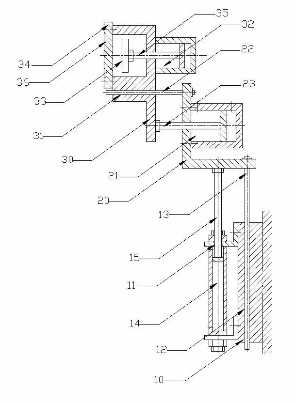
[0023] See attached figure 1 , the injection machine auxiliary manipulator according to the present invention includes: a lifting structure, an opening and closing structure, and a material loading structure;

[0024] The lifting structure includes a fixed base 10, a fixed bracket 11 fixed on the fixed base 10, and a cylinder 14 fixed on the fixed bracket 11. It is pre-set to precisely control the moving distance of the manipulator loading structure in the vertical direction.

[0025] The opening and closing structure includes a mounting seat 20 , and the mounting seat 20 is fixedly connected with the piston rod 15 of the cylinder 14 . It also includes a cylinder 21 fixed on the mounting seat 20. The function of the cyli...


PUM


Abstract

The invention discloses an auxiliary manipulator for an injection machine, and the auxiliary manipulator is formed by a lifting structure, an opening and closing structure and a material loading structure, and comprises a fixed base seat (10), a fixed support (11) and a cylinder (14) fixedly arranged on the fixed support (11); a mounting seat (20) is fixedly connected with a piston rod (15) of the cylinder (14); a mounting support seat (30) is fixedly connected with a piston rod (23) of a cylinder (21); a cylinder (32) is fixedly arranged on the mounting support seat (30); a permanent magnet (33) is fixedly arranged on a piston rod (35) of the cylinder (32); and a die assembly plate (34) is arranged on the mounting support seat (30). The auxiliary manipulator for the injection machine is fixedly arranged on a rack of the injection machine by the fixed base seat (10), the movement of the manipulator in the vertical direction and the horizontal direction is controlled by the lifting mechanism and the opening and closing mechanism, so metal inserts mounted on the die assembly plate (34) in advance can be accurately mounted into a die cavity of a die of the injection machine, and thereby automatic material loading is realized.

Description

technical field [0001] The invention relates to an auxiliary manipulator for an injection machine, in particular to an auxiliary material loading manipulator. Background technique [0002] Bonded NdFeB permanent magnets have developed extremely rapidly since their appearance, and have become an indispensable functional material in modern industry. The conventional production process of bonded NdFeB permanent magnet mainly includes: compression molding process, injection molding process and extrusion molding process. The products produced by the above three processes have different characteristics. Compression molding mainly produces ring-shaped magnets, which are mainly used in hard disk drives and optical drives. The extrusion molding process mainly produces thin-walled, large-diameter magnets, or slender strip magnets, which are widely used in the field of printers. The injection molding process uses a large-scale injection machine to heat and melt the mixed magnetic pow...

Claims


Application Information

Patent Timeline
IPC IPC(8): B22F3/22
Inventor 周志建李纲
Owner 上海三环磁性材料有限公司
Why Eureka
Try Eureka