
Laser cutting machine

A laser cutting machine and laser head technology, applied in laser welding equipment, welding equipment, metal processing equipment, etc., can solve the problems of long focal length, plate thickness limitation, and inconvenient feeding process of cutting machine, etc., to achieve efficient and accurate feeding process, The effect of slowing down the fit error and improving the cutting working environment

Inactive Publication Date: 2012-07-11
江苏大华激光科技开发有限公司
View PDF11 Cites 26 Cited by
  • Summary
  • Abstract
  • Description
  • Claims
  • Application Information

AI Technical Summary

Problems solved by technology

[0002] There is only one focusing lens in the laser head of the existing laser cutting machine, and the height of the laser head is relatively fixed. However, in the laser cutting operation, it is often necessary to cut steel plates and other materials with different thicknesses. Considering the cutting quality, it is better to cut thicker steel plates. A focused laser beam with a longer focal length is required, and a focused laser beam with a shorter focal length is required to cut thinner steel plates, so the thickness of the plate that the cutting machine can cut is limited
In addition, the dust particles generated by the operation of the existing laser cutting machine will affect the working environment, and the feeding process of the existing cutting machine is also relatively inconvenient

Method used


Image

  • Laser cutting machine
  • Laser cutting machine
  • Laser cutting machine

Examples


Embodiment Construction

[0016] The present invention will be further described below with reference to the accompanying drawings.

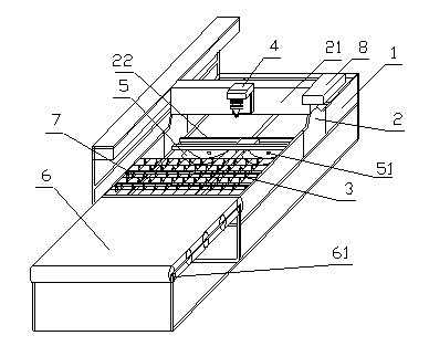
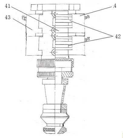
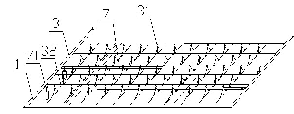
[0017] combine figure 1 , figure 2 as well as image 3 , the laser cutting machine includes a bed frame 1, a transverse support 2, a mesh plate 3 and a laser head 4, the transverse support 2 is slidably arranged on the bed frame 1, and the laser head 4 is placed on the beam 21 in the middle of the upper end of the transverse support 2. The plate 3 is placed in the working part of the middle of the bed frame 1, the grid nodes 31 of the screen plate 3 are raised, and a valley 32 is formed between the adjacent nodes of the grid. The laser cutting machine also includes a vacuum hopper 5, a feeding Roller mechanism 6, a number of driving rollers 7, the driving roller 7 is arranged above the screen plate 3 of the bed frame and corresponds to the feeding roller mechanism 6, and the two ends of the driving roller 7 are respectively connected with the pneumatic (or hydraulic) ...


PUM


Abstract

The invention relates to the field of cutting tools, in particular to a laser cutting machine, which comprises a bedstock, a horizontal support, a screen, a laser head, a dust absorption hopper, a feeding roller mechanism and a plurality of driving rollers. The horizontal support is slidably arranged on the bedstock, the laser head is arranged in the middle of the upper end of the horizontal support, the screen is arranged on an operating portion in the middle of the bedstock, grid nodes of the screen project, a trench is formed between each two adjacent grid nodes, the feeding roller mechanism is arranged at a feeding end of the bedstock, the driving rollers are arranged above the screen of the bedstock and correspond to the feeding roller mechanism, the dust absorption hopper is arranged on the lower portion of the horizontal support, a focusing lens cavity is arranged in the laser head, and a plurality of focusing lens clamping slots are arranged in the focusing lens cavity. As the clamping slots for mounting focusing lenses with different focal lengths are arranged on the laser head, the same cutting machine can be used for conveniently cutting plates with a certain difference in thickness.

Description

technical field [0001] The invention relates to the field of cutting tools, in particular to a laser cutting machine. Background technique [0002] There is only one focusing lens in the laser head of the existing laser cutting machine, and the height of the laser head is relatively fixed. However, in the laser cutting operation, it is often necessary to cut steel plates and other materials with different thicknesses. Considering the cutting quality, it is necessary to cut thicker steel plates. A focused laser beam with a longer focal length is required, and a focused beam with a shorter focal length is required to cut thinner steel sheets, so the thickness of the sheet that can be cut by the cutting machine is limited. In addition, the smoke and dust particles generated by the operation of the existing laser cutting machine will affect the working environment, and the feeding process of the existing cutting machine is also relatively inconvenient. SUMMARY OF THE INVENTION...

Claims


Application Information

Patent Timeline
Patent Type & Authority Applications(China)
IPC IPC(8): B23K26/38B23K26/04B23K26/16B23K26/42B23K26/035B23K26/70
Inventor 彭绍益
Owner 江苏大华激光科技开发有限公司
Learn More