Self-centering and work piece clamping device for working table and control method of self-centering and work piece clamping device

A technology of clamping device and workbench, which is applied in the direction of positioning device, automatic control device, feeding device, etc., can solve the problems of low clamping efficiency, high purchase cost, and injury to operators, so as to improve clamping efficiency and device structure Simple, cost-effective production

Inactive Publication Date: 2012-07-11
SANY GRP
View PDF6 Cites 7 Cited by
  • Summary
  • Abstract
  • Description
  • Claims
  • Application Information

AI Technical Summary

Problems solved by technology

Most of the machine tools currently in use do not have the functions of workpiece self-centering and workpiece automatic clamping. Some outsourced self-centering workbenches are expensive. For small-scale enterprises, the purchase cost is too high and it is difficult to bear.
In addition, many workpiece clamping devices on the workbench are manual clamping structures, and the clamping efficiency is relatively low, which seriously affects the production efficiency of the enterprise.
[0003] At present, most of the workpiece clamping devices on the machine tool workbench are manual clamping devices, and the clamping efficiency is relatively low. When manual clamping is used, it may hurt the operator and cause unnecessary accidents.
In addition, in the process of workpi

Method used


Image

  • Self-centering and work piece clamping device for working table and control method of self-centering and work piece clamping device
  • Self-centering and work piece clamping device for working table and control method of self-centering and work piece clamping device

Examples


Embodiment Construction

[0038] The present invention will be described in further detail below in conjunction with the accompanying drawings and specific embodiments. The specific embodiments described here are only used to explain the present invention, and are not used to limit the protection scope of the present invention.

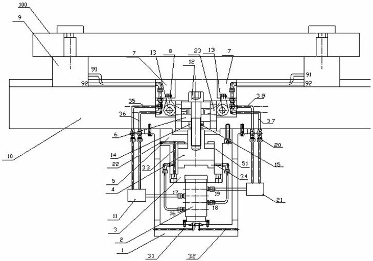
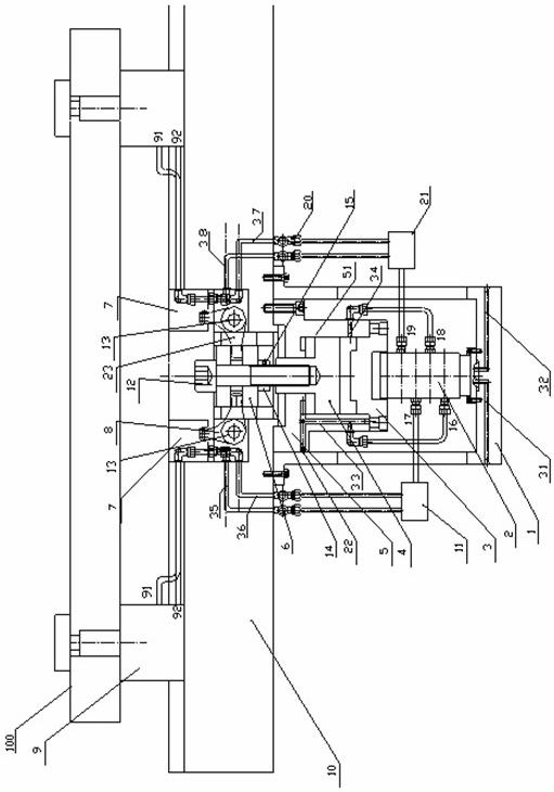
[0039] combined reference figure 1 The shown workbench 10 self-centering and workpiece clamping device specifically includes a workbench 10; a fixed support 1 is fixed under the workbench 10 and remains concentric with the workbench 10, and the fixed support 1 The first oil passage 31 and the second oil passage 32 are arranged in it; the integrated solenoid valve 2 is arranged at the bottom of the fixed bracket 1 involved, and the integrated solenoid valve 2 includes a first oil outlet 16, a second oil outlet 17, The third oil outlet 18, the fourth oil outlet 19 and two oil inlets ( figure 1 unmarked), the two oil inlets are respectively connected to the first oil passage 31...


PUM


Abstract

The invention discloses a self-centering and work piece clamping device for a working table and a control method of the self-centering and work piece clamping device. The device comprises hydraulic claws which are pushed by a piston to close or open. The work piece is clamped by compression method instead of clamping method in the prior art, so as to prevent deformation of thin-wall parts during the clamping process. The closed or opened state of each oil outlet is controlled by an integrated solenoid valve, so that the work piece has the self-centering effect. The invention has the advantages that the device changes the conventional manual centering and inner/outer-side clamping structure in the prior art, increases the work piece clamping efficiency, prevents deformation of the work piece during the clamping process, improves the reliability of work piece machining, and reduces the production cost.

Description

technical field [0001] The present invention relates to workbench self-centering and workpiece clamping, in particular to a workbench self-centering and workpiece clamping device and a control method thereof. Background technique [0002] my country is a country with a large demand for machine tools, and it needs to import a large number of machine tools from abroad every year, especially large and heavy machine tools. With the development of modern large-scale production, the national manufacturing industry is increasingly dependent on modern production equipment. As the core of manufacturing production equipment - machine tools, naturally more and more attention has been paid. Most of the machine tools currently in use do not have the functions of workpiece self-centering and workpiece automatic clamping. Some outsourced self-centering workbenches are expensive. For small-scale enterprises, the purchase cost is too high and it is difficult to bear . In addition, many wor...

Claims


Application Information

Patent Timeline
IPC IPC(8): B23Q3/08B23Q15/20
Inventor 谢卫其吴飞荣禇朋朋
Owner SANY GRP
Why Eureka
Try Eureka