
Speed-reducing wheel-rim driving system using motor as power vibration absorber

A dynamic vibration absorber and wheel-side drive technology, which is applied in the power plant, motion deposition, elastic suspension, etc., can solve the problems that the mass of the dynamic vibration absorber should not be too large, increase the curb weight of the whole vehicle, and reduce the driving mileage. Improved vertical performance, low manufacturing cost and high power density

Inactive Publication Date: 2012-07-11
TONGJI UNIV
View PDF5 Cites 3 Cited by
  • Summary
  • Abstract
  • Description
  • Claims
  • Application Information

AI Technical Summary

Problems solved by technology

However, the traditional dynamic shock absorber method needs to suspend an additional mass block on the wheel, which takes up space and increases the curb weight of the vehicle, thereby reducing the driving mileage
In addition, affected by the above factors, the quality of the installed dynamic vibration absorber should not be too large, so the vibration absorption effect is limited

Method used


Image

  • Speed-reducing wheel-rim driving system using motor as power vibration absorber
  • Speed-reducing wheel-rim driving system using motor as power vibration absorber
  • Speed-reducing wheel-rim driving system using motor as power vibration absorber

Examples


Embodiment Construction

[0034] Please refer to the accompanying drawings for a further description of the present invention.

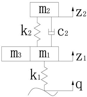
[0035] figure 1 It is a 1 / 4 vehicle two-degree-of-freedom vibration model diagram of a traditional wheel-drive electric vehicle, and the mass m3 of the motor 1 is the unsprung mass.

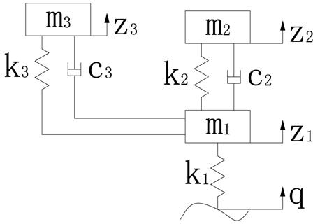
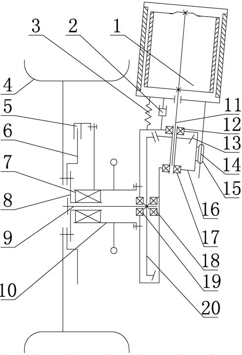
[0036] figure 2 It is a three-degree-of-freedom vibration model diagram of a 1 / 4 vehicle equipped with a shock absorber. The motor acts as a deceleration wheel drive system for a dynamic shock absorber, where m2 is 1 / 4 of the body mass, and m1 is the unsprung mass, mainly including the wheels , wheel rim 4, braking system rotating element 6, braking system non-rotating element 5, half shaft 9, steering knuckle 10, small bevel gear 13 with internal spline, large bevel gear 20, reduction box 16 and other qualities, m3 is the mass of the dynamic shock absorber, that is, the mass of the motor 1. By properly setting the damping coefficient C3 of the damping element of the dynamic shock absorber an...


PUM


Abstract

The invention discloses a speed-reducing wheel-rim driving system using a motor as a power vibration absorber. The power is outputted to a small bevel gear by the output shaft of the motor; the small bevel gear is meshed with a large bevel gear, the power is outputted to a semiaxis by the large bevel gear; the section of the semiaxis, which extends into a wheel hub, is provided with an external spline; and the power is transferred to a wheel rim by the wheel hub; the wheel hub, the wheel rim and a rotating element of a braking system are fixedly connected and rotate together; the output shaft of the motor matches with the small bevel gear to transfer power; and the output shaft of the motor slides along the axis of the small bevel gear. The motor is suspended on the wheel, and the motor mass is transferred into the power vibration absorber mass from the unsprung mass. The speed reducing wheel rim driving system has low manufacturing cost and high transmission efficiency and is beneficial to exerting the advantages of high efficiency and large power density of the high-speed motor.

Description

technical field [0001] The invention relates to the field of electric vehicle chassis and transmission, in particular to a reduction wheel drive system in which a motor acts as a dynamic shock absorber. Background technique [0002] At present, the main structural feature of the wheel-side electric drive system represented by electric wheels is that the drive motor is installed in or near the drive wheel, which has the advantages of short drive transmission chain, efficient transmission, and compact structure. At the same time, the torque of each driving wheel in the wheel drive system can be independently controlled. The wheel motor is not only the information unit of the car, but also the fast-response control execution unit, which is conducive to the realization of high-performance control functions that are difficult to achieve on traditional cars, thereby improving harsh conditions. Driving performance under road conditions. [0003] However, in the general wheel driv...

Claims


Application Information

Patent Timeline
IPC IPC(8): B60G13/00B60K7/00
Inventor 陈辛波唐峰陆承超余卓平张擎宇
Owner TONGJI UNIV
Learn More