Elevator brake control device and control method thereof

A technology for elevator brakes and control devices, which is used in transportation, packaging, elevators, etc., can solve problems such as slippage of traction ropes and traction sheaves, and achieve the effects of extending service life, reducing accident risks, and stabilizing parking.

Active Publication Date: 2012-07-11
HITACHI ELEVATOR SHANGHAI
View PDF6 Cites 12 Cited by
  • Summary
  • Abstract
  • Description
  • Claims
  • Application Information

AI Technical Summary

Problems solved by technology

[0006] The purpose of the present invention is to provide an elevator brake control device and its control method to solve the technical problem existing in the prior art that slipping occurs between the traction rope and the traction sheave in the process of using the brake to decelerate or stop the elevator

Method used


Image

  • Elevator brake control device and control method thereof
  • Elevator brake control device and control method thereof
  • Elevator brake control device and control method thereof

Examples


Embodiment Construction

[0043] The specific implementations of the elevator brake control device and the control method thereof of the present invention will be described in detail below in conjunction with the accompanying drawings, but the implementation of the present invention is not limited to the following implementations.

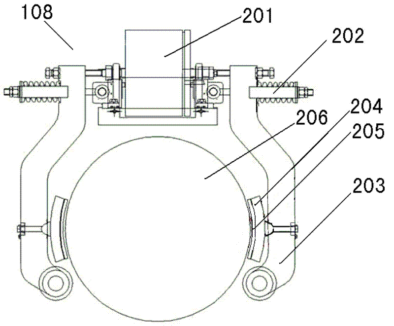
[0044] Such as figure 2 As shown, the brake 108 is generally a two-way thrust elevator brake, including a winding coil 201 with an iron core, a compression spring 202, a brake arm 203, a brake shoe 204, a brake band 205, a brake disc 206, etc., wherein two The bar brake arm 203 is shaped like a clip, and the current passing through the winding coil 201 with the iron core will generate an outward force, pushing the two brake arms 203 outward, while the two brake arms 203 outside are compressed. The spring 202 will generate an inward force to close the two brake arms 203 . During the movement of the car 101, the above two forces will reach a balance, the two brake arms 203 ...


PUM


Abstract

The invention relates to an elevator brake control device and a control method thereof. The elevator brake control device comprises a brake switch, a hoisting rope speed measurement device, a hoisting wheel speed measurement device, a speed comparison unit, a restarting unit and a main control unit, wherein the hoisting rope speed measurement device and the hoisting wheel speed measurement device are respectively connected with the speed comparison unit; and the speed comparison unit is connected with the brake switch sequentially through the restarting unit and the main control unit. According to the elevator brake control device and the control method thereof, damage to an elevator caused by a slip phenomenon between a hoisting rope and hoisting wheels during deacceleration or braking of the elevator is reduced effectively, and the service life of the hoisting rope and the service life of the hoisting wheels are prolonged, so that the elevator is stopped more stably, and the accident risk is reduced.

Description

technical field [0001] The invention relates to an elevator brake, in particular to an elevator brake control device and a control method thereof. Background technique [0002] The power system in the elevator is the traction system. The traction system is mainly composed of a traction machine, a traction rope, a guide wheel, and a reverse rope wheel. The main function of the traction system is to output and transmit power so that the elevator can run normally. The traction machine is the main power equipment of the elevator. It is composed of a motor, a brake, a reduction box, and a traction sheave. The traction wire rope is connected to the car at one end through the traction sheave, and the counterweight device at the other end. [0003] The control system of the elevator controls the motor and the brake so that the car can reciprocate up and down along the guide rails in the hoistway, and the elevator performs vertical transportation tasks. [0004] figure 1 It is a sc...

Claims


Application Information

Patent Timeline
Patent Type & Authority Applications(China)
IPC IPC(8): B66B1/32B66B5/00
Inventor 吴红兵中山徹也卢晓民刘少维
Owner HITACHI ELEVATOR SHANGHAI
Why Eureka
Try Eureka