Carbon dioxide recovery method and carbon-dioxide-recovery-type steam power generation system

A carbon dioxide and power generation system technology, applied in the direction of direct carbon dioxide emission reduction, chemical instruments and methods, separation methods, etc., can solve problems such as excessive reduction of power station output, increase of turbine output, insufficient condensate to recover the total heat of carbon dioxide, etc.

Inactive Publication Date: 2012-07-11
KK TOSHIBA
View PDF6 Cites 10 Cited by
  • Summary
  • Abstract
  • Description
  • Claims
  • Application Information

AI Technical Summary

Problems solved by technology

[0004] However, there has always been a problem: the amount of condensate is not enough to recover the total heat of carbon dioxide
For this reason, there has always been the problem that the reco

Method used


Image

  • Carbon dioxide recovery method and carbon-dioxide-recovery-type steam power generation system
  • Carbon dioxide recovery method and carbon-dioxide-recovery-type steam power generation system
  • Carbon dioxide recovery method and carbon-dioxide-recovery-type steam power generation system

Examples


no. 1 example

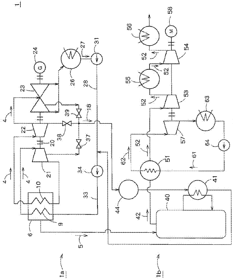
[0016] figure 1 The general structure of the carbon dioxide recovery type steam power generation system according to the first embodiment of the present invention is illustrated. The carbon dioxide recovery type steam power generation system 1 includes: a steam power generation device 1a that generates turbine steam 4 through combustion of fuel and rotates the turbine to generate power; and a carbon dioxide recovery device 1b that absorbs carbon dioxide contained in exhaust gas 5 by use The absorbing liquid is used to recover carbon dioxide from the exhaust gas 5 generated in the boiler 6.

[0017] The boiler 6 is supplied with fuel and air for combustion, and the fuel is burned in the furnace, thereby generating turbine steam 4 and generating exhaust gas 5. The boiler 6 includes: a superheater 9 that generates main steam by heating the turbine steam 4 through combustion in the furnace; and a reheater 10 that is arranged adjacent to the superheater 9 and the reheater 10 The turb...

no. 2 example

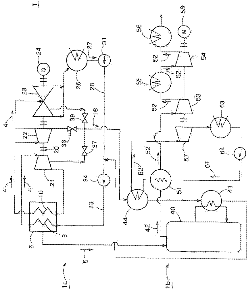
[0032] figure 2 The schematic structure of the carbon dioxide recovery type steam power generation system according to the second embodiment of the present invention is illustrated. This embodiment is the same as figure 1 The difference of the first embodiment shown in is that the cooling water 61 performs heat exchange between the carbon dioxide gas 42 containing water vapor and the steam 18 for heating the reboiler. in figure 2 In, and figure 1 The same parts as those of the first embodiment shown in are indicated by the same reference numerals. The description will not be repeated.

[0033] Such as figure 2 As shown, the cooling water 61 is in CO 2 The condenser 51 exchanges heat with the carbon dioxide gas 42 containing water vapor, and then exchanges heat with the steam 18 as the heat source of the reboiler 41 in the temperature reduction unit 44. The steam 62 generated by the heat exchange between the carbon dioxide gas 42 containing water vapor and the steam 18 is supp...

no. 3 example

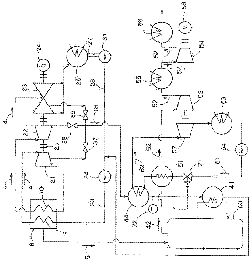
[0036] image 3 The schematic structure of the carbon dioxide recovery type steam power generation system according to the third embodiment of the present invention is illustrated. This embodiment is the same as figure 2 The difference in the second embodiment shown in is that the system includes a valve 71 that adjusts the flow rate of the cooling water 61, and a control unit that measures the temperature of the steam 18 whose temperature is lowered by the temperature reduction unit 44 and controls the opening degree of the valve 71 72. in image 3 In, and figure 2 The parts that are the same as those of the second embodiment shown in are indicated by the same reference numerals. The description will not be repeated.

[0037] Valve 71 is set at pump 64 and CO 2 Between the condenser 51, and according to the opening degree of the valve 71, the valve 71 can change the supply to the CO 2 The flow rate of the cooling water 61 of the condenser 51 and the temperature reducing unit ...


PUM


Abstract

The invention relates to a carbon dioxide recovery method and a carbon-dioxide-recovery-type steam power generation system. According to one embodiment, a carbon-dioxide-recovery-type steam power generation system comprises a boiler that produces steam and generates an exhaust gas by combusting fuel, a first turbine that is connected to a generator and is rotationally driven by the steam supplied from the boiler, an absorption tower that is supplied with the exhaust gas from the boiler and allows carbon dioxide contained in the exhaust gas to be absorbed into an absorption liquid, a regeneration tower that is supplied with the absorption liquid absorbing the carbon dioxide from the absorption tower, discharges a carbon dioxide gas from the absorption liquid, and discharges the carbon dioxide gas, a reboiler that heats the absorption liquid from the regeneration tower and supplies the generated steam to the regeneration tower, a condenser that removes moisture from the carbon dioxide gas, discharged from the regeneration tower, by condensing the carbon dioxide gas using cooling water, a compressor that compresses the carbon dioxide gas from which the moisture is removed by the condenser, and a second turbine that drives the compressor The steam produced by the cooling water recovering the heat from the carbon dioxide gas in the condenser is supplied to the first turbine or the second turbine.

Description

Technical field [0001] The embodiments described herein generally relate to carbon dioxide recovery type steam power generation systems and carbon dioxide recovery methods. Background technique [0002] In power generation systems such as thermal power stations that use a large amount of fossil fuels, the amine absorption method is used as a method to remove and recover carbon dioxide, one of the causes of global warming. However, in the amine absorption method, thermal energy obtained from a large amount of low pressure (for example, about 0.3 MPa) steam is required to regenerate the absorption liquid that has absorbed carbon dioxide. [0003] In order to compensate for this thermal energy, a method is proposed in which the heat of the absorbed carbon dioxide and the heat generated by compressing the carbon dioxide to a high pressure suitable for injecting carbon dioxide into the ground (for example, about 8 MPa) are performed. After the heat exchange between them, the condensate...

Claims


Application Information

Patent Timeline
IPC IPC(8): F01K11/02B01D53/14
CPCF01K25/103F01K25/06F01K13/00Y02C10/06Y02E20/14B01D53/1475F01K17/06B01D53/1425B01D53/265B01D53/343B01D53/62B01D2252/204B01D2257/504B01D2257/80B01D2258/0283Y02A50/20Y02C20/40Y02E20/32
Inventor 村上裕哉冲田信雄高桥武雄高柳干男须贺威夫笹沼健史清国寿久北村英夫
Owner KK TOSHIBA
Why Eureka
Try Eureka