Method For Operating A Motor Vehicle With Two Turbochargers

A technology for turbochargers and automobiles, applied in the direction of machines/engines, combustion engines, internal combustion piston engines, etc., can solve the problem of rough speed and achieve low cost

Inactive Publication Date: 2012-07-11
AUDI AG
View PDF0 Cites 3 Cited by
  • Summary
  • Abstract
  • Description
  • Claims
  • Application Information

AI Technical Summary

Problems solved by technology

Furthermore, the known method has the disadvantage that the temperature difference between compressor inlet and compressor outlet represents only a rough indicator of the rotational speed

Method used


Image

  • Method For Operating A Motor Vehicle With Two Turbochargers
  • Method For Operating A Motor Vehicle With Two Turbochargers

Examples


Embodiment Construction

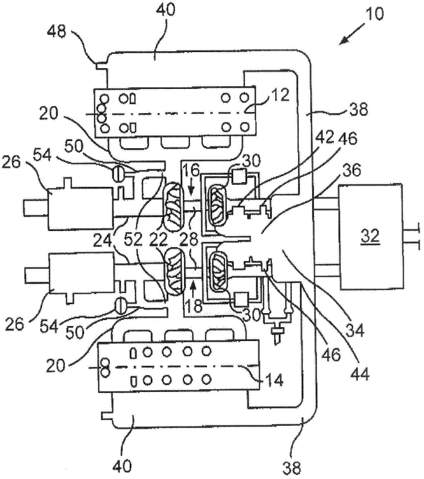
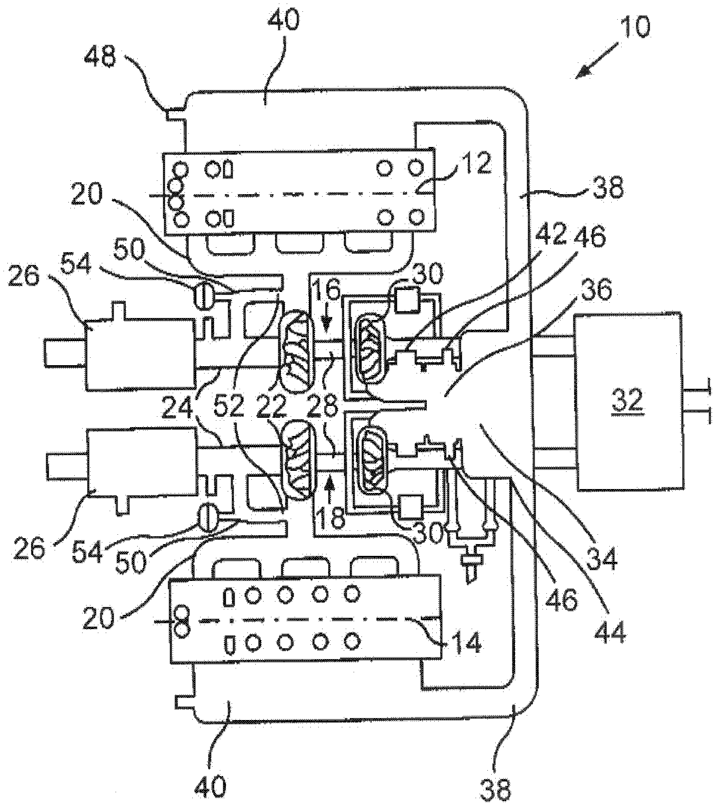
[0020] In this example, the engine, generally designated 10 , is an 8-cylinder V-engine having two block bases 12 , 14 . A turbocharger 16 , 18 for the charge air supply of the respective cylinder base 12 , 14 is assigned to each cylinder base 12 , 14 . Here too, the two turbochargers 16 , 18 can supply charge air into a common collecting container / chamber. In this case, the respective exhaust manifold 20 conducts exhaust gas from the cylinder base 12 , 14 to the turbine 22 of the respective turbocharger 16 , 18 . The exhaust gas flow then passes through each exhaust conduit 24 to an exhaust catalyst 26 .

[0021] A turbine 22 driven by exhaust gas drives a compressor wheel / rotor 30 of the turbochargers 16 , 18 via a shaft 28 . Ambient air drawn in through one or more air filters 32 is compressed by a compressor wheel 30 and delivered to a charge air cooler 34 . In this case, the air flow can be regulated via a throttle valve 36 . The compressed and cooled air exiting the ...


PUM


Abstract

The present invention relates to a method for operating a motor vehicle with two turbochargers (16,18). A cylinder group is assigned for each of the two turbochargers, wherein the temperature of pressurized air flow is measured for each turbocharger (16,18) at downstream of a compressor impeller (30) of each turbocharger (16,18) in a flowing direction of the pressurized air, and furthermore the difference of each temperature is formed. The difference between the temperatures of the two turbochargers (16,18) indicates that one of the turbochargers (16,18) has a rotating speed which enlarges relative to the other turbochargers (16,18). Therefore, the damage of the turbochargers (16,18) caused by rotation speed overlimit can be reliably prevented based on temperature measurement.

Description

technical field [0001] The invention relates to a method for operating a motor vehicle with two turbochargers. Background technique [0002] Motor vehicles with a turbocharger arrangement are generally known from the prior art, in which a cylinder bank is assigned to each turbocharger, for example a single block base of a V-engine. Each turbocharger supplies the associated cylinder bank with compressed charge air, the exhaust gas of the respective cylinder bank driving the turbine of the associated turbocharger. This is also known as a parallel twin-turbo arrangement. Also known are systems in which a plurality of turbochargers feed into a common chamber, from which all cylinders are supplied. [0003] The delivery efficiency of the turbocharger must be adjusted based on the operating conditions of the engine. Furthermore, a part of the exhaust gas flow can be directed past the turbine of the turbocharger by means of a so-called exhaust bypass valve. The rotational speed...

Claims


Application Information

Patent Timeline
Patent Type & Authority Applications(China)
IPC IPC(8): F02B37/007F02B37/18F02B37/22
CPCF01N13/04F02B37/18Y02T10/144F02B37/007F02B37/22F01N13/011Y02T10/12
Inventor R·A·卡歇尔
Owner AUDI AG
Why Eureka
Try Eureka