Ratchet-type tensioner

A tensioner, ratchet-type technology, applied in the directions of machines/engines, belts/chains/gears, valve devices, etc., can solve the problems of easy generation of hitting sound, large-scale tensioner, inability to reduce hitting sound, etc., to achieve stable The effect of starting, actually starting

Inactive Publication Date: 2012-07-11
TSUBAKIMOTO CHAIN CO
View PDF6 Cites 0 Cited by
  • Summary
  • Abstract
  • Description
  • Claims
  • Application Information

AI Technical Summary

Problems solved by technology

However, there is a problem that the greater the amount of movement of the plunger, the less likely it is to reduce the rattling sound when the engine is started.
[0010] In addition, in order to solve the problem that the knocking sound is likely to be generated when the engine is started, although an additional orifice structure and an oil storage structure can be adopted, and the plunger biasing spring 518 is replaced with a spring suitable for high loads, etc. countermeasures, but for this reason This not only increases the number of parts and manufacturing cost, but also causes the problem of increasing the size of the tensioner itself

Method used


Image

  • Ratchet-type tensioner
  • Ratchet-type tensioner
  • Ratchet-type tensioner

Examples


Embodiment

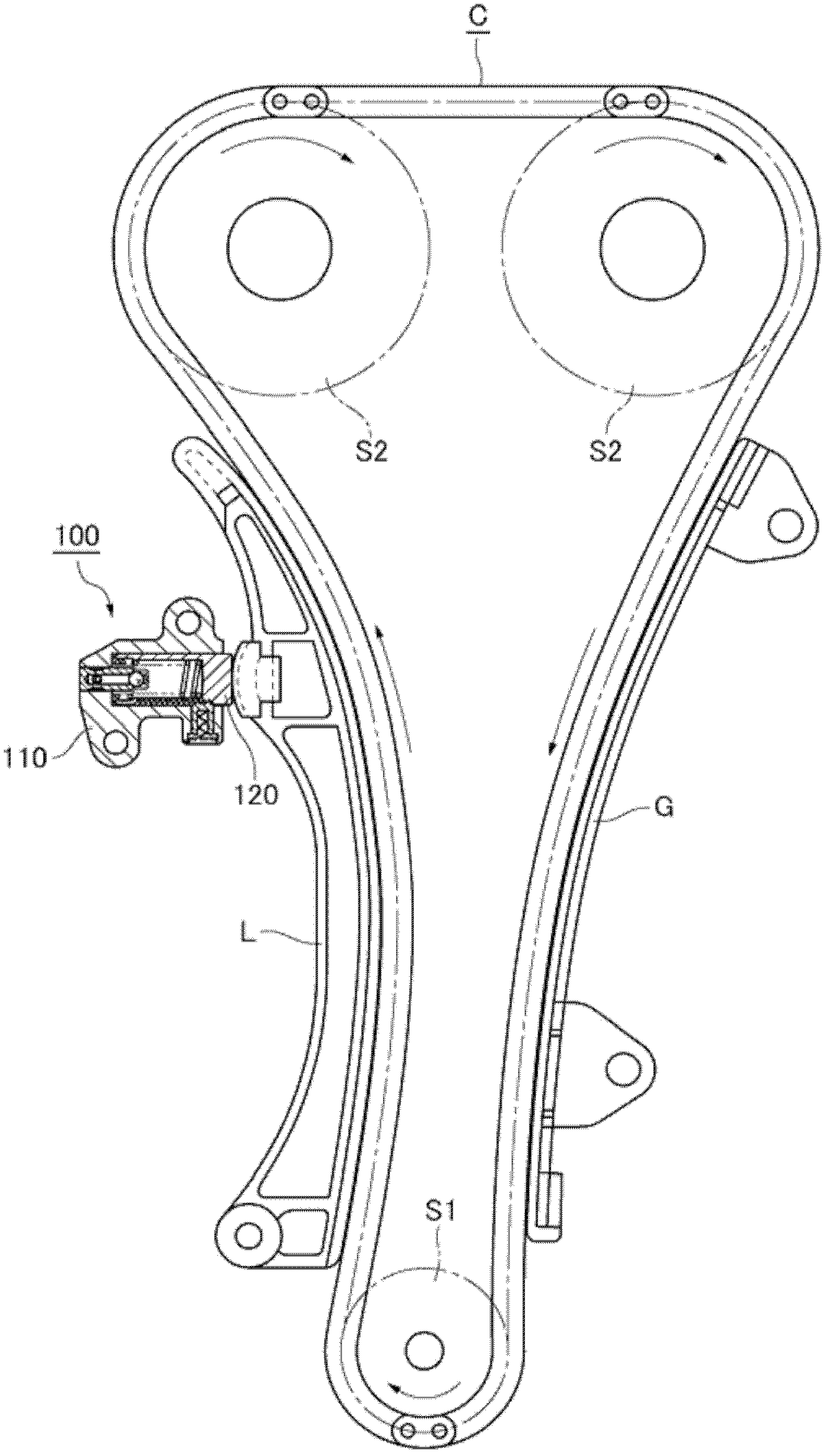
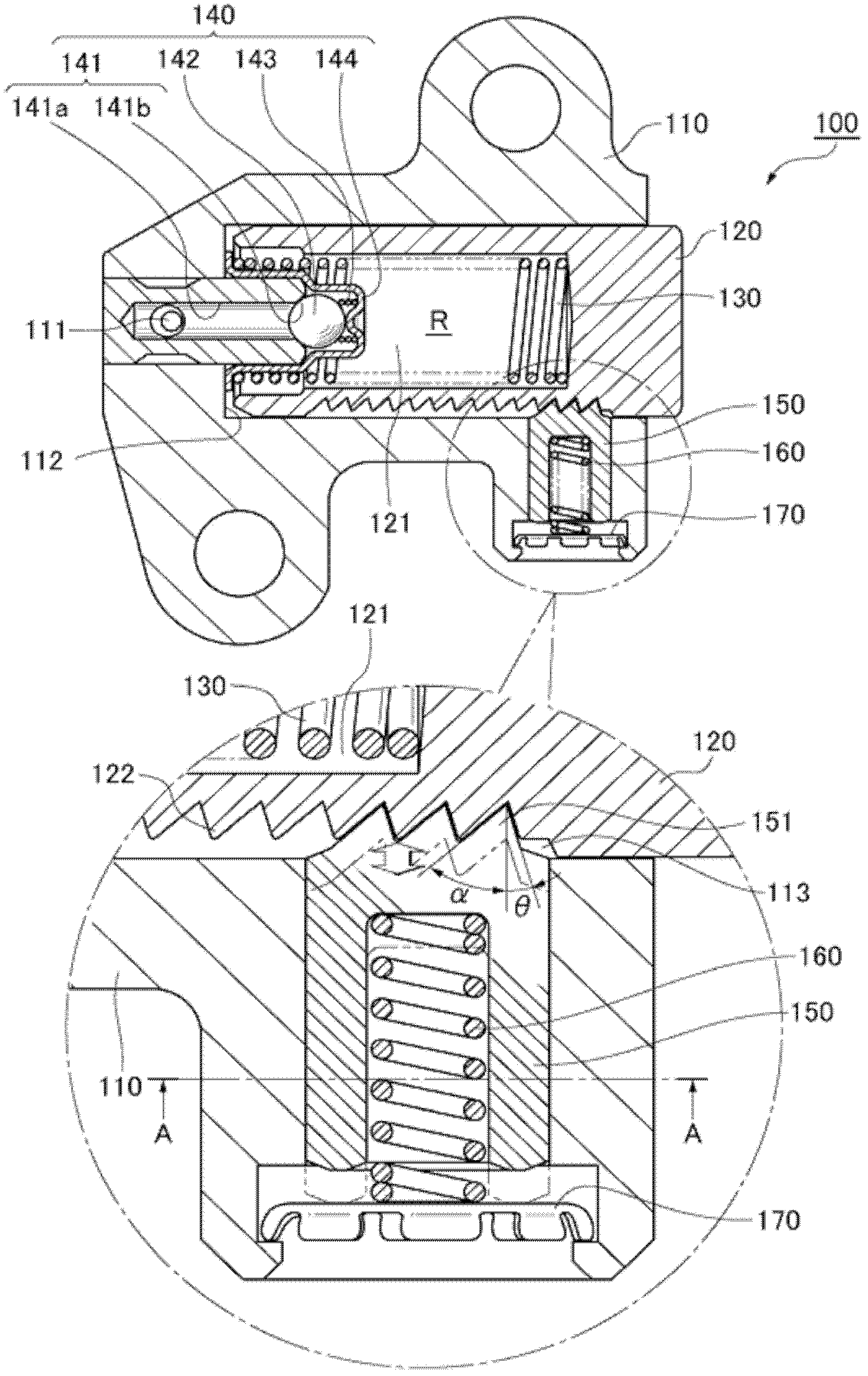
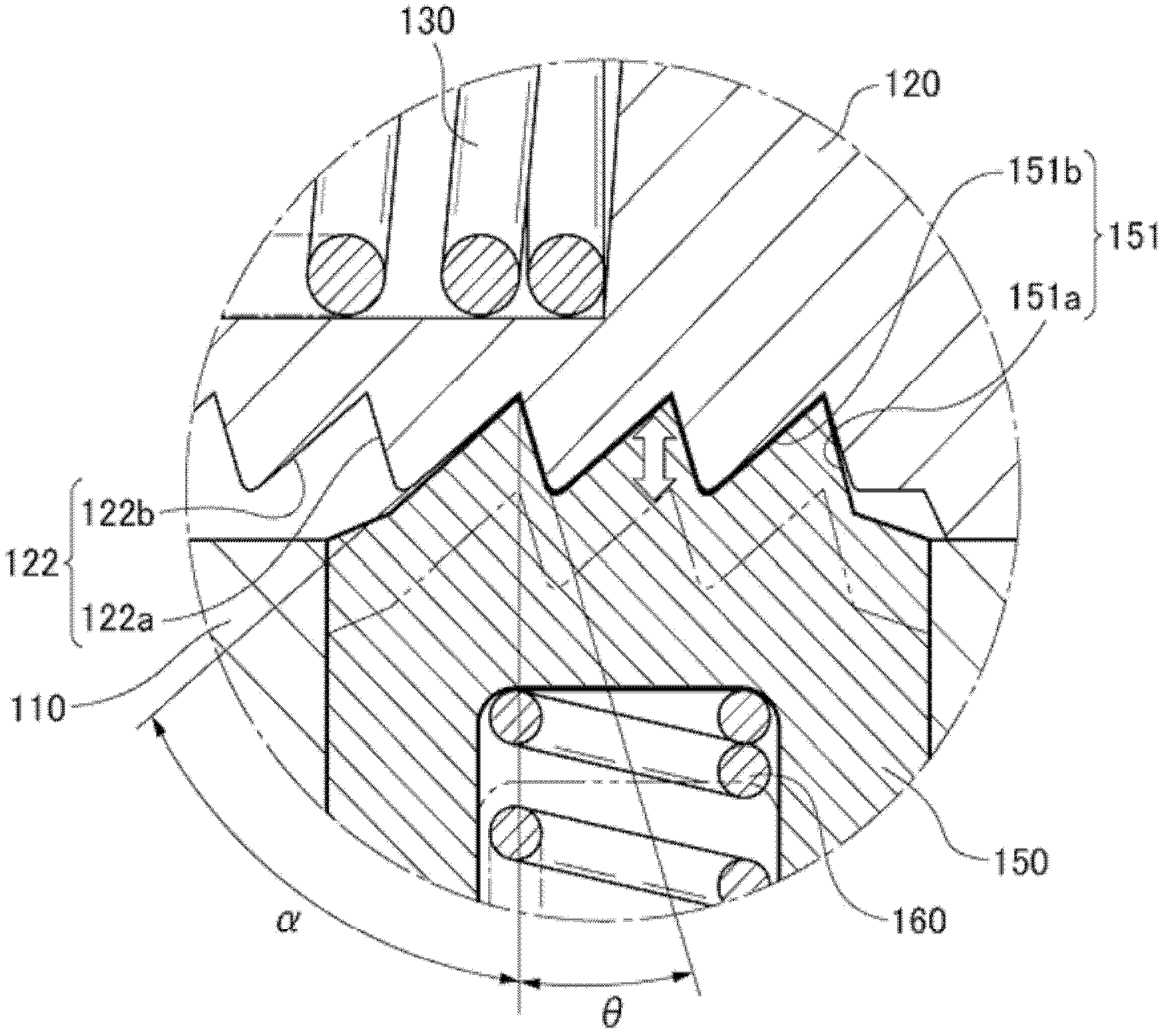
[0111] Below, combine Figure 1 to Figure 8 A ratchet tensioner 100 according to one embodiment of the present invention will be described.

[0112] figure 1 It is the use state diagram of the ratchet tensioner 100 of the first embodiment of the present invention; figure 2 for figure 1 An enlarged cross-sectional view of significant portions of the illustrated ratchet tensioner 100; image 3 It is an enlarged view of rack teeth and ratchet teeth; Figure 4 for figure 2 Enlarged view of A-A shown; Figure 5 Exploded view of the ratchet, the spring for applying force to the ratchet and the plug for locking the spring; Image 6 It is a schematic diagram of the meshing state accompanied by the protruding action of the plunger when the engine is started; Figure 7 It is a schematic diagram of the meshing state accompanying the plunger retreat action when the engine is started; Figure 8 It is a schematic diagram of the meshing state when the plunger starts to retreat du...


PUM


Abstract

The invention provides a ratchet-type tensioner in which a ratchet mechanism, comprising a plunger and a ratchet, operates with reliability and stability, faulty operation is avoided, flapping noises are reduced, and at the same time, seizing of the plunger due to excessive chain tension is avoided. The ratchet-type tensioner (100) makes an engagement matching mechanism for engaging a ratchet teeth (151) of said ratchet (150) with a rack teeth (122) on the side surface of said plunger without twisting across the whole range of face width be configured in a condition of stopping an outer peripheral surface of the ratchet (150) form turning with respect to an inner peripheral surface of said ratchet storing hole (113).

Description

technical field [0001] The present invention relates to a ratchet tensioner for applying tension to a timing chain driving a camshaft of an engine. Background technique [0002] A conventionally known tensioner is used to drive the timing chain of the camshaft of the engine, so that the protruding force generated by the spring and the external oil pressure acts on the plunger, which is slidably inserted into the casing and is connected with the An oil chamber is formed between the housings to apply tension to the timing chain. [0003] As such existing tensioners such as Figure 12 As shown, the tensioner 500 has: a piston 526, which is slidably inserted in the housing 512 in a direction perpendicular to the sliding direction of the plunger 514, and an auxiliary oil chamber 520 is formed between the housing 512; The oil pressure acts on the oil passage 544 of the auxiliary oil chamber 520; the air chamber 528 is divided by the outer shell 512 and the piston 526 on the oppos...

Claims


Application Information

Patent Timeline
Patent Type & Authority Applications(China)
IPC IPC(8): F16H7/08F01L1/348
CPCF16H2007/0853F16H2007/0812F16H2007/0806F16H7/0848F16H7/08
Inventor 吉田修榑松勇二前田宗裕
Owner TSUBAKIMOTO CHAIN CO
Why Eureka
Try Eureka