Reverse sealing structure of emergency cut-off valve for gas

A technology of sealing structure and cut-off valve, which is applied in the direction of lifting valve, valve device, engine components, etc., can solve the problems such as difficult design of spring, and achieve the effect of cost reduction, design difficulty and simple structure

Inactive Publication Date: 2012-07-11
北京市燕山工业燃气设备有限公司
View PDF7 Cites 4 Cited by
  • Summary
  • Abstract
  • Description
  • Claims
  • Application Information

AI Technical Summary

Problems solved by technology

[0003] In order to overcome the shortcomings of the existing gas emergency cut-off valve structure, the present invention proposes a structure to solve the problem that the spring is not easy to design

Method used


Image

  • Reverse sealing structure of emergency cut-off valve for gas
  • Reverse sealing structure of emergency cut-off valve for gas
  • Reverse sealing structure of emergency cut-off valve for gas

Examples


Embodiment Construction

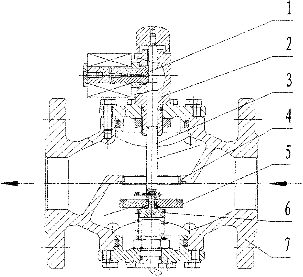
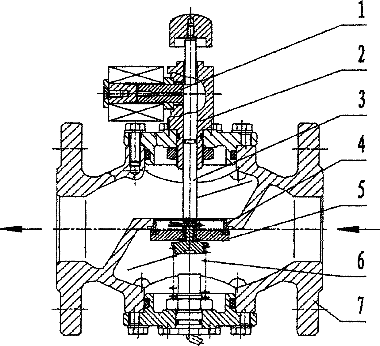
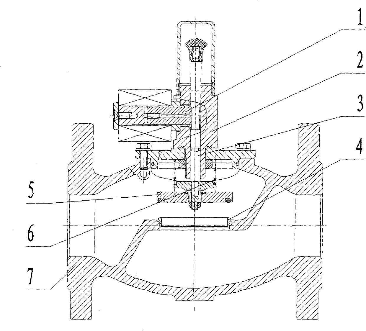
[0015] Implementation see figure 1 , figure 2 , this reverse sealing structure includes a cut-off controller that controls the closing of the valve, a valve cover that supports and guides, a valve stem for connection and control, and a valve seat for sealing, which is used to cover the valve seat tightly to cut off the pipeline. The valve disc that circulates gas in the middle, the spring that provides a certain power for the valve stem disc, and the valve body that acts as a frame.

[0016] Working process of the present invention:

[0017] When the valve is in the pipeline and is in the open state ( figure 1 ), the valve stem is subjected to the upward pull-out force generated by the pressure difference inside and outside the valve body, the upward elastic force of the spring and the downward limiting force of the cut-off controller. When the cut-off controller receives the cut-off signal and begins to act, the limiting force on the valve stem is withdrawn. The valve cl...


PUM


Abstract

The invention relates to a reverse sealing structure of an emergency cut-off valve for gas, in particular to an emergency cut-off valve structure for gas and with a large working pressure range. The reverse sealing structure of the emergency cut-off valve for gas is characterized in that the closing direction of a valve is the same with the F1 direction of rod pulling force, and the pressure difference of the inside and the outside of a valve body is utilized to assist to close the valve. The reverse sealing structure of the emergency cut-off valve for gas has the advantages that 1 the structure is simple, and the cost is reduced slightly compared with an existing commonly-used structure; 2 the requirements can be met without the large spring force P, and the design difficulty is reduced; and 3 due to the fact that the dependence of a spring to provided spring force is reduced, the working pressure range of the valve is large.

Description

technical field [0001] The invention relates to a reverse sealing structure of a gas emergency cut-off valve, in particular to a structure of a gas emergency cut-off valve with a relatively large working pressure range (see figure 1 , figure 2 ). Background technique [0002] At present, the sealing structures commonly used in domestic gas emergency shut-off valves are closed from top to bottom (see image 3 ), in the working state of the cut-off valve, there will be a pressure difference between the inside and outside of the valve body, so the valve stem is subjected to a pulling force F to the outside of the valve body 1 , due to structural reasons, the spring force P should be greater than the pull-out force F 1 The sum of the friction force f, the opening force F is the spring force P, the friction force f and the valve seat pressure F 2 Therefore, when the working pressure range is large, the spring design is more difficult. Although some manufacturers have introdu...

Claims


Application Information

Patent Timeline
Patent Type & Authority Applications(China)
IPC IPC(8): F16K1/00
Inventor 海明璋高健中
Owner 北京市燕山工业燃气设备有限公司
Why Eureka
Try Eureka