Magnetic valve with emptying function
A magnetic and valve technology, applied in the direction of lift valve, valve details, valve device, etc., can solve the problems of technical difficulty of processing methods, dripping, material waste, etc., and achieve the effect of low processing and production cost, easy production and processing, and simple manufacturing.
- Summary
- Abstract
- Description
- Claims
- Application Information
AI Technical Summary
Problems solved by technology
Method used
Image

Examples
Embodiment Construction
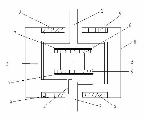
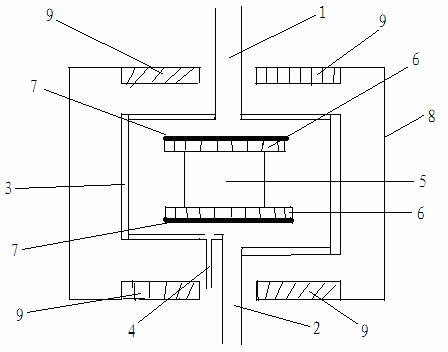
[0018] Accompanying drawing is a kind of specific embodiment of the present invention. This embodiment includes a valve chamber 3 with an inlet 1 and an outlet 2 respectively at both ends, an air inlet 4 on the same side as the outlet 2 is arranged on the valve chamber 3, and the air inlet 4 and the outlet 2 are not on the same plane, the valve chamber 3 is provided with a free-swimming movable column 5, and both ends of the movable column 5 are provided with powerful magnets 6, and the outside of the powerful magnet 6 is wrapped with a silicone gasket 7; the outside of the valve chamber 3 is wrapped with a plastic link body 8. The two ends of the plastic link body 8 are provided with a magnetic control 9, and the middle of the magnetic control 9 passes through the inlet 1 or the outlet 2; the valve chamber 3 is a closed plastic cylinder, and the plastic cylinder is divided into upper and lower halves, and the middle is provided with a Connect the thread; the powerful magnets ...
PUM
 Abstract
Description
Claims
Application Information
PatSnap Eureka turns technology decisions into work you can execute. Powered by our Innovation Knowledge Graph, it runs expert workflows across engineering, life sciences, materials and intellectual property. Get your review-ready output in minutes.


